logo
Home > Products >
Cable Fault Locator
>
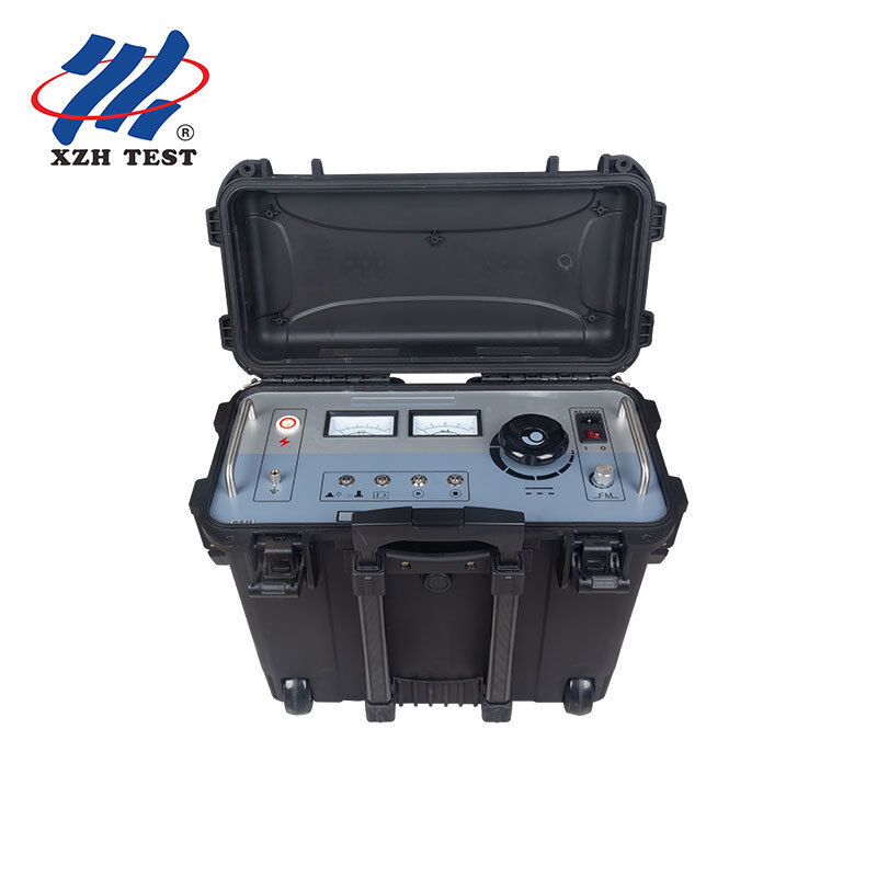
500kV Cable Sheath Fault Locator XHHD523L for 10kV-500kV HV Cable Outer Sheath Testing and Ground Fault Pinpointing

500kV Cable Sheath Fault Locator XHHD523L for 10kV-500kV HV Cable Outer Sheath Testing and Ground Fault Pinpointing

Product Details:
Place of Origin: Xi'an, Shaanxi, China
Brand Name: XZH TEST
Certification: CE/ISO
Model Number: XHHD523L
Detail Information
Place of Origin:
Xi'an, Shaanxi, China
Brand Name:
XZH TEST
Certification:
CE/ISO
Model Number:
XHHD523L
Input Voltage:
220V (±10%), 50Hz (±2Hz)
Output Voltage:
0 ~ 10kV (square Wave) Adjustable
Output Curren:
0~200mA
Output Capacity:
2kVA
Color:
Black
Gross Weight:
48kg
Package Dimension:
64*42*70cm
Highlight:

High Light

Highlight:

500kV Cable Sheath Fault Locator

,

HV Outer Sheath Ground Fault Detection

,

Step Voltage Cable Pinpointer

Trading Information
Minimum Order Quantity:
1 unit
Price:
Price Negotiable
Packaging Details:
Wooden case
Delivery Time:
5-8 work days
Payment Terms:
T/T
Supply Ability:
500 units/month
Product Description
500kV Cable Sheath Fault Locator — XHHD523L Model: XHHD523L | 10kV–500kV | Step Voltage + DC Withstand

Designed for: HV Cable Commissioning Teams, Utility Cable Maintenance Departments, Cable Engineering Contractors, Substation Test Personnel

Core Value: Detect, locate, and verify outer sheath insulation faults on 10kV to 500kV single-core and three-core power cables — using step voltage pinpointing and DC withstand testing in one portable instrument.

The Cable Sheath Problem

On high-voltage XLPE power cables rated 110kV and above, the outer sheath is the first line of defense. Manufactured from HDPE material and factory-tested at DC 25kV/5min with leakage currents as low as tens of microamps, a healthy sheath offers decades of protection. But once the cable is laid in the ground, reality sets in — backfill damage during installation, termite penetration after years of operation, water ingress at grounding boxes, and mechanical stress at trifurcation joints progressively degrade sheath integrity.

When the sheath fails, the metallic screen becomes exposed to ground moisture, initiating corrosion and eventually screen breakdown. Traditional fault location methods — designed for conductor-to-conductor or conductor-to-ground faults — cannot reliably detect these sheath-to-ground defects. The XHHD523L is purpose-built to fill this gap, delivering controlled high-voltage pulses to the sheath layer and precisely locating the leakage point using the step voltage method.


Who Needs the XHHD523L
User Profile Application Scenario
HV Cable Commissioning Engineers Post-installation sheath integrity verification before energizing new 110kV-500kV cable circuits. GB50150-2006 requires DC withstand testing of outer sheaths before handover acceptance.
Utility Cable Maintenance Teams Annual preventive testing of in-service cable sheaths. Early detection of incipient defects before they escalate into screen breakdown and forced outages.
Fault Investigation Specialists Locating sheath ground faults on buried cables where the defect may be several years old, buried deep, or surrounded by complex soil conditions — cases where trial excavation is prohibitively expensive.
Construction & Installation Contractors Verifying sheath condition immediately after cable laying and before backfilling, when any installation damage is still accessible for repair.

Dual Operating Modes — One-Key Toggle
Fault Locating Mode 0-10kV square wave output with adjustable frequency (0.2Hz-5Hz). Connect the high-voltage lead to the cable sheath, deploy the A-frame receiver along the cable route, and follow the step voltage gradient to the exact fault point. Green indicator confirms locating mode active.
DC Withstand Testing Mode Continuous DC output up to 10kV / 200mA for sheath withstand voltage verification per GB50150-2006. Monitor leakage current in real time via the mA meter. Red indicator confirms withstand mode active. One-key switch between modes without reconnecting cables.

Why This Matters in the Field: A commissioning engineer finishes the 10kV/1min sheath withstand test on a new 110kV circuit — and the leakage current spikes. Rather than packing up and returning to the office to plan an excavation, they press one button to switch to locating mode, deploy the A-frame, and pinpoint the defect while still on site. Same instrument, same cable connection, no reconfiguration.


Technical Specifications
Parameter Specification
Input Power AC 220V ±10%, 50Hz ±2Hz
Output Voltage 0–10 kV DC (square wave, adjustable)
Output Current 0–200 mA
Output Capacity 2 kVA
Frequency Range 0.2Hz – 5Hz (continuously adjustable in locating mode)
Applicable Cable Range 10kV–500kV single-core and three-core HV/EHV power cables
Test Standard Compliance GB50150-2006 (cable outer sheath handover and preventive testing), cross-interconnect system testing
Safety Protections Zero-position start interlock, automatic discharge on stop (HV drops to zero when output is cut), over-current protection switch, over-voltage protection, over-temperature protection
Display Dual analog meters — kV voltmeter + mA ammeter, intuitive real-time monitoring
Operating Modes Fault locating (step voltage) / DC withstand (one-key toggle with LED mode indicators)
Package Dimensions 64 × 42 × 70 cm
Gross Weight 48 kg
Brand / Origin XZH TEST / Xi'an, Shaanxi, China
Certification CE

Receiver System — Precision Detection at the Surface

The XHHD523L includes a dedicated receiver unit designed for two detection methods:

Step Voltage Method (A-Frame)

The A-frame sub-rack is deployed along the cable route at regular intervals. The receiver measures the voltage gradient between the two ground probes — the signal amplitude and polarity change as the operator passes over the fault point, pinpointing the sheath defect to within a sub-meter radius at the surface.

Receiver Clamp Method

For cable route tracing and sheath fault pre-location in areas where ground probe insertion is impractical (paved surfaces, rocky terrain), the receiver clamp inductively couples to the cable, detecting signal strength variations that indicate the fault zone.

Receiver Control Function
Micro-Ampere Meter Indicates signal magnitude and polarity — needle deflection direction confirms approaching or passing the fault point
Signal Input Connection port for A-frame or receiver clamp
Zero Adjustment Calibrates reference baseline in Mode I (amplified mode for weak signals)
Adjustment Knob Controls input signal amplitude — increase sensitivity for deep-buried cables, reduce for shallow installations
Mode Switch Mode I: Amplified mode for weak signal environments (A-frame + clamp). Mode II: Direct mode for strong signal environments (A-frame only, no internal amplifier). 0: Power off

Eight Built-in Safety Features
  1. Zero-Start Interlock: High voltage cannot be energized unless the voltage adjustment knob is fully counterclockwise. The start button illuminates only when zero position is confirmed — preventing accidental energization at high voltage
  2. Automatic Self-Discharge: When high-voltage output is terminated — either by Stop button or power interruption — the internal circuit automatically bleeds residual charge to zero. No manual discharge procedure required
  3. Over-Current Protection: Dedicated overcurrent protection switch with blue LED indicator. When enabled, the system automatically trips if output current exceeds the safe threshold
  4. Over-Voltage Protection: Internal voltage clamping prevents output from exceeding the 10kV maximum rating under any operating condition
  5. Over-Temperature Protection: Thermal sensor monitors internal temperature and disables HV output if safe operating limits are exceeded — critical for extended field use in hot climates
  6. Grounded Enclosure: Instrument grounding column must be connected to station earth before operation — provides a verified safety reference for all internal protection circuits
  7. Dual Analog Meter Monitoring: Independent kV and mA meters provide real-time, unambiguous readings — no digital display lag or ambiguity in bright sunlight
  8. 8A System Fuse: Accessible rear-panel fuse provides final overcurrent protection for the AC input circuit

What’s Included
Component Description
Main Unit (Sheath Fault Locator) Host instrument with 0-10kV square wave generator, dual-mode selector, dual meters, and safety systems
High-Voltage Connection Cable Connects main unit HV output terminal to cable sheath under test
Receiver Unit Handheld receiver with micro-ampere meter, sensitivity adjustment, and dual mode (I/II) operation
A-Frame Sub-Rack For step voltage method fault pinpointing — two ground probes with calibrated spacing
Receiver Clamp Inductive clamp for cable tracing and fault zone pre-location on paved surfaces
Power Cord AC 220V instrument power cable
Ground Wire Instrument safety earth connection
Spare Fuse 8A spare fuse for AC input circuit

Standard Testing Workflow
  1. Sheath Insulation Assessment: Connect the main unit to the cable sheath. Select DC Withstand mode (red indicator). Apply 10kV DC and monitor the mA meter — leakage current below tens of microamps confirms sheath integrity
  2. Fault Confirmation: If leakage current is elevated, the sheath has a ground fault. Note the approximate leakage level for reference during pinpointing
  3. Mode Switch: Press the mode toggle button — green indicator confirms locating mode. Adjust output frequency (0.2Hz-5Hz) based on cable length and burial depth
  4. Step Voltage Pinpointing: Deploy the A-frame along the cable route. The receiver's micro-ampere meter will show increasing signal strength approaching the fault, needle reversal as you pass it, and null at the exact fault location
  5. Mark and Repair: Mark the pinpointed location on the surface. The defect is typically accessible within a targeted 1-meter excavation — compared to tens of meters of trenching without prior location
  6. Post-Repair Verification: After sheath repair, repeat the DC withstand test to confirm restoration of sheath integrity before re-energizing the cable

Operational Precautions
  • Only qualified high-voltage test personnel may operate this instrument
  • Always connect the grounding column to a verified station earth before energizing
  • The voltage adjustment knob must be fully counterclockwise (zero position, start button illuminated) before pressing Start
  • Do not touch HV output terminals, connection cables, or the cable sheath while the HV indicator is active
  • Press Stop immediately if abnormal meter readings, arcing sounds, or unusual odors are detected
  • After stopping HV output, verify the voltmeter reads zero before disconnecting any cables — automatic discharge is reliable but always visually confirm