logo
Home > Products >
Cable Fault Locator
>
Cable Outer Sheath Fault Locator XHHD523L for Cross-Interconnection System Testing and EHV Cable Commissioning

Cable Outer Sheath Fault Locator XHHD523L for Cross-Interconnection System Testing and EHV Cable Commissioning

Product Details:
Place of Origin: Xi'an,Shaanxi,China
Brand Name: XZH TEST
Certification: CE ISO
Model Number: XHHD523L
Detail Information
Place of Origin:
Xi'an,Shaanxi,China
Brand Name:
XZH TEST
Certification:
CE ISO
Model Number:
XHHD523L
Highlight:

High Light

Highlight:

Cross-Interconnection Cable Tester

,

EHV Sheath Fault Pinpointing System

,

Cable Commissioning DC Withstand

Trading Information
Minimum Order Quantity:
1unit
Packaging Details:
wooden packaging
Payment Terms:
T/T
Supply Ability:
500 units per month
Product Description
Cable Outer Sheath Fault Locator for Cross-Interconnection Systems — XHHD523L Model: XHHD523L | 10kV–500kV | Cross-Bonding + Sheath Diagnostics

Designed for: Transmission Asset Managers, EPC Commissioning Contractors, HV Cable System Engineers, Cross-Bonding Link Box Specialists

Core Value: Verify sheath integrity and cross-interconnection systems on EHV cable circuits — from link box diagnostics to step voltage fault pinpointing — in a single portable instrument compliant with GB50150-2006.

The Cross-Interconnection Challenge

On single-core high voltage cables rated 110kV and above, the metallic sheath acts as both an electrostatic shield and a fault current return path. To minimize circulating current losses, these sheaths are configured in cross-bonded arrangements through link boxes at regular intervals along the cable route — typically every 500-1000 meters for a full transposition cycle. Each link box connects the three-phase sheaths in a specific rotational pattern, with Surge Voltage Limiters (SVLs) installed to protect the sheath insulation during transient overvoltage events.

This cross-interconnection system introduces a unique testing challenge: the sheath is not a single continuous conductor from end to end, but a segmented network interconnected through buried link boxes. A sheath fault anywhere in this network — whether on the cable outer jacket, inside a link box, or across an SVL — can produce misleading test results when measured from the cable terminations alone. The XHHD523L addresses this by providing both the DC withstand capability to identify that a sheath defect exists, and the step voltage pinpointing capability to locate exactly where in the cross-bonded network the defect resides.


Who Needs the XHHD523L — A Different Perspective
User ProfileCritical Need Addressed
Transmission Asset ManagersManaging a portfolio of 110kV-500kV cable circuits across multiple substations. The XHHD523L provides standardized sheath condition data for asset health indexing — identifying which circuits need intervention before sheath degradation escalates into a screen-to-ground fault requiring an unplanned outage.
EPC Commissioning ContractorsHandover testing of newly installed cable systems per GB50150-2006. The XHHD523L performs both the mandatory 10kV/1min DC withstand test on the outer sheath AND provides immediate fault pinpointing if the sheath fails — eliminating the back-and-forth between separate test and location instruments during the commissioning window.
Cross-Bonding System EngineersDiagnosing link box and SVL integrity on in-service cable circuits. By injecting test signals at specific sheath segments and measuring the response, the XHHD523L helps distinguish between a genuine outer jacket fault and a degraded SVL or water-ingressed link box — two problems with very different repair strategies.
Renewable Energy EPC TeamsLarge-scale solar farms and offshore wind cable landfalls involve kilometers of 33kV-220kV buried collector circuits. Sheath faults introduced during cable laying or backfilling must be located and repaired before the project handover deadline. The XHHD523L's one-key mode toggle lets the commissioning team move from withstand test to fault location without reconfiguring the test setup.

Technical Specifications
ParameterSpecification
Input PowerAC 220V ±10%, 50Hz ±2Hz
Output Voltage0–10 kV DC (square wave, continuously adjustable)
Output Current0–200 mA
Output Capacity2 kVA
Frequency Range0.2 Hz – 5 Hz (continuously adjustable in locating mode)
Applicable Cables10kV–500kV single-core and three-core power cables
Testing ModesFault locating (step voltage) / DC withstand — one-key toggle with LED indicators (red = withstand, green = locating)
Compliant StandardsGB50150-2006 (cable outer sheath handover test and preventive test), cross-interconnection system testing requirements
Safety ProtectionsZero-position start interlock, auto-discharge on stop (HV drops to zero automatically), over-current/over-voltage/over-temperature protection, overcurrent protection switch with blue LED indicator
DisplayDual analog meters (kV voltmeter + mA ammeter) — real-time, unambiguous readings in all lighting conditions
Package Dimensions64 * 42 * 70 cm
Gross Weight48 kg
Brand / OriginXZH TEST / Xi'an, Shaanxi, China
CertificationCE, ISO

Receiver System — Step Voltage and Signal Tracing Methods
Receiver ControlFunction
Micro-Ampere MeterIndicates signal magnitude and polarity — needle deflection direction confirms whether the operator is approaching or has passed the fault point during step voltage surveying
Signal InputAccepts connection from either the A-frame sub-rack (step voltage method) or the receiver clamp (inductive signal tracing for paved surfaces)
Zero AdjustmentCalibrates the reference baseline in Mode I (amplified mode) for consistent fault detection in weak-signal environments such as deep-buried cables or high-resistance soil conditions
Sensitivity AdjustmentControls input signal amplitude — increase for deep-buried cables, decrease for shallow installations or strong signals to maintain meter readability
Mode Switch (I / 0 / II)Mode I: Amplified mode for weak signals (A-frame + clamp supported). Mode II: Direct mode for strong signals (A-frame only, bypasses internal amplifier). 0: Power off position

Field Advantage — No Blind Area: Unlike TDR-based cable fault locators that have a measurement dead zone near the test terminal, the XHHD523L step voltage method has zero blind area. It can locate sheath faults immediately adjacent to the cable termination point — a capability critical for commissioning tests where sheath damage often occurs near the termination during cable gland installation.


Panel Controls — Logical Operating Sequence

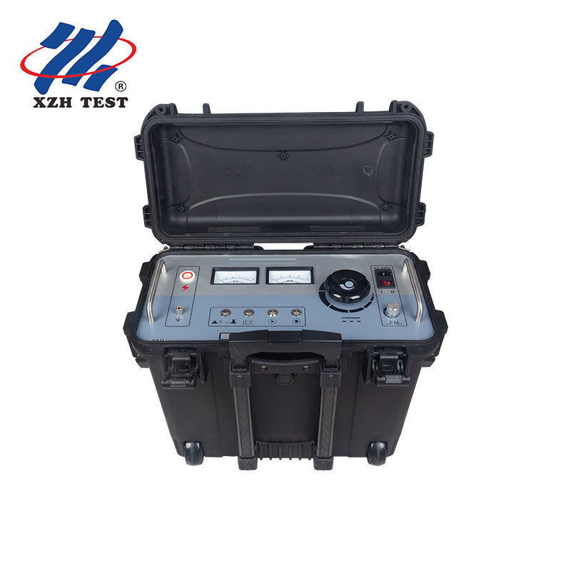
The XHHD523L front panel is laid out in a left-to-right operating flow, minimizing operator error during field deployment:

  1. HV Output Terminal: Dedicated DC high-voltage output connection for the cable sheath under test
  2. kV Voltmeter: Real-time high-voltage output indication
  3. mA Ammeter: Output current monitoring — essential for detecting abnormal leakage during withstand testing
  4. System Fuse: 220VAC power supply fuse — user-replaceable via external socket
  5. AC Power Input: IEC power socket for 220VAC instrument supply
  6. Power Switch: I = AC powered, 0 = shutdown
  7. Frequency Adjustment: Adjusts pulse output frequency in locating mode (0.2Hz-5Hz range)
  8. Voltage Adjustment: Zero-position start — must be fully counterclockwise (start button illuminates) before HV can be energized. Clockwise rotation increases output from 0 to 10kV
  9. HV Stop Button: Cuts HV output and triggers automatic capacitor discharge. HV indicator extinguishes when output is safely at zero
  10. HV Start Button: Effective only when voltage adjustment is at zero position (button illuminated). Press to energize HV output
  11. Overcurrent Protection Switch: Blue LED illuminated = overcurrent protection active, LED off = protection disabled
  12. Mode Toggle Button: Red LED = withstand voltage mode, Green LED = fault locating mode. One-key toggle between modes
  13. Grounding Column: Instrument grounding point — must be connected to verified station earth before operation

Cross-Interconnection System Test Workflow
  1. Isolate and Prepare: De-energize the cable circuit. Open cross-bonding link boxes at both ends of the segment under test. This isolates the sheath section for individual assessment — essential because an interconnected healthy segment can mask a fault in an adjacent segment
  2. Segment Identification: At each accessible link box, identify the sheath segment to be tested. Record the segment length and the link box identification for your test report
  3. DC Withstand Test: Connect the XHHD523L to the isolated sheath segment. In withstand mode (red LED), apply 10kV DC per GB50150-2006. Monitor the mA meter for abnormal leakage current indicating sheath degradation
  4. Fault Assessment: If the withstand test passes (leakage within specification), record the result and proceed to the next segment. If the sheath fails, note the leakage current level for reference during pinpointing
  5. Mode Switch and Pinpoint: Toggle to locating mode (green LED). Inject the 0-10kV square wave signal at the optimal frequency for the cable length. Deploy the A-frame receiver along the cable route between link boxes — the receiver's micro-ampere meter guides you to the exact fault position
  6. Excavate and Repair: The step voltage method typically pinpoints the defect within a 1-meter radius. Excavate at the indicated position, perform the sheath repair (outer jacket patch or cable joint replacement), and repeat the DC withstand test to verify restoration

Why Sheath Diagnostics Matter — The Asset Management Perspective

For a transmission asset manager responsible for tens or hundreds of kilometers of 110kV-500kV cable circuits, sheath condition data is not just a test result — it is the leading indicator for future maintenance expenditure. A cable with a compromised sheath is on a countdown to screen corrosion, possible screen breakdown, and eventual forced outage. The XHHD523L enables a condition-based maintenance strategy:

  • Baseline Commissioning Data: Establish sheath integrity baselines for every new cable circuit at handover — creating a reference for all future preventive maintenance tests
  • Scheduled Preventive Testing: Annual or biennial sheath withstand tests on in-service circuits detect degradation trends before they reach failure thresholds
  • Targeted Repairs: When a sheath defect is identified, pinpoint it precisely rather than replacing an entire cable section — reducing repair costs by an order of magnitude compared to blind excavation or full cable replacement