Description
This cable fault locator is a special instrument for measuring and analyzing the status and fault distance of power cables. Cable speed measurement, cable length test, cable fault distance test.
Technical specification
|
Sampling frequency
|
80MHz
|
|
Low voltage pulse amplitude
|
100V±15%
|
|
Ranging range
|
≥65km
|
|
Test range
|
300m/1km/5km/25km/65km
|
|
Pulse width
|
0.125uS/0.50uS/2.50uS/7.25uS/10.0uS
|
|
Minimum resolution
|
0.1m
|
|
Test blind area
|
≤20m
|
|
Measurement error
|
≤±(0.5%×L+1m), L is the cable length
|
|
Power supply mode
|
charging AC110V~240V, 50Hz/60Hz
|

The system has an automatic ranging function
Low voltage pulse sampling interface
High voltage flashover(ICE) sampling interface
User Interface Introduction
1. Display: 10.1-inch full-color TFT touchscreen display;
2. Grounding: Safety grounding terminal;
3. Signal: Low-voltage pulse method pulse signal output interface, high-voltage flashover method sampler, and multi-pulse method coupler receiving signal input interface;
4. USB: Import waveform files to a computer via USB communication;
5. Power Socket: Instrument operating power supply, AC 220V connection port/charging port;
6. Fuse: Fuse installation location for the AC 220V power supply system;
7. Power Switch: "I" position, using AC 220V power to power the system;
"II" position, using the internal battery to power the system; when the "Power Socket" is connected to AC 220V power, the battery is also charged;
"O" position, turning off the system power;
8. Amplitude: Adjust the amplitude knob when acquiring waveforms to change the amplitude of the acquired waveform;
9. Operation Knob: Rotary button for system interface operation control, rotate to select and press to confirm;
10. Displacement: When acquiring waveforms, adjust the displacement knob to change the baseline height of the acquired waveform.

 Your message must be between 20-3,000 characters!
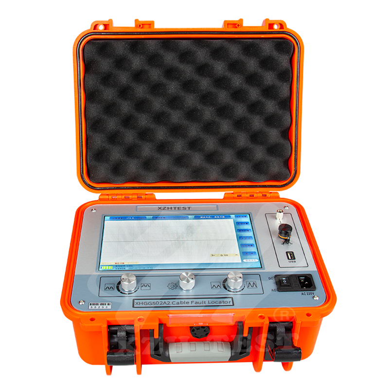
Overall Rating
Rating Snapshot
The following is the distribution of all ratingsAll Reviews