XHHV512-12L
Ideal for impulse discharge when testing faults in 12kV-and-below cables; it also works for DC withstand voltage tests on other electrical equipment.
Product Features:
Accurate real-time voltage measurement on the high-voltage side; Zero-position start protection for enhanced safety and reliability; Unique high-voltage measurement design, allowing the voltmeter to indicate the capacitor voltage value in real-time even when stopped, providing operators with complete control over the high voltage; Discharge time can be arbitrarily set within appropriate intervals.

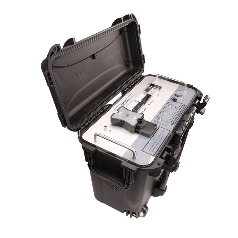
Panel Function Description
1. Safety Ground: Grounds the instrument casing to prevent the casing from becoming live or to personnel from getting an electric shock.
2. Discharge Button: When the high voltage is off, pressing this button manually discharges the internal charge.
3. Start Button/Zero Position Indicator: When the zero position indicator is lit (yellow), it indicates the instrument is in the zero position. Pressing the start button will activate the high voltage output. When the zero position indicator is off, it indicates the instrument is not in the zero position. Rotate the voltage adjustment knob counterclockwise to the zero position; the zero position indicator will then light up. Pressing the start button again will activate the high voltage output.
4. Stop Button/High Voltage Indicator: When the test is complete or an abnormality occurs, pressing this button will cut off the high voltage output. The high voltage indicator will light up to indicate that the high voltage output has started; the indicator will turn off to indicate that the high voltage output has stopped.
5. Overcurrent Protection Switch: When pressed, the overcurrent protection function is activated; when released, the instrument has triggered overcurrent protection. 6. Voltage Adjustment: After turning on the device, first turn this knob counterclockwise to the end, then press the start button. Then adjust clockwise to increase the output high voltage from low to high, and counterclockwise to decrease the output high voltage from high to low.
7. Power Switch: "Position 1" indicates that AC 220V power is on to supply power to the system; "Position 0" indicates that AC 220V power is off to supply power to the system.
8. Fuse Holder: The location for installing fuses in the AC 220V power supply system.
9. Power Socket: The instrument's operating power supply, AC 220V connection port.
10. Time Setting: Sets the discharge time interval.
11. Ammeter: Indicates the current on the high-voltage side.
12. Voltmeter: A kV meter indicating the high-voltage output voltage.
13. High Voltage Output (EMP): Connect the high-voltage output line during impulse discharge.
14. High Voltage Output (DC): Connect the high-voltage output line during DC withstand voltage testing.

 Your message must be between 20-3,000 characters!