Designed for: Power Utility Cable Fault Teams, 35kV Distribution Network Maintenance Contractors, Industrial High-Voltage Testing Service Providers
Core Value: Pull-rod portable DC impulse generator with 2μF capacitor delivering 0-1024J discharge energy for 35kV and below cable fault detection. Triple protection + zero-position interlock + real-time standby voltmeter — full 35kV impulse capability in a single-operator portable form factor.
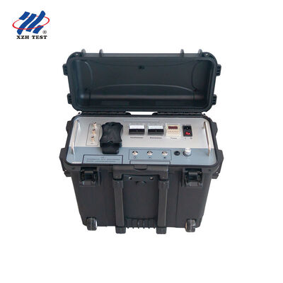
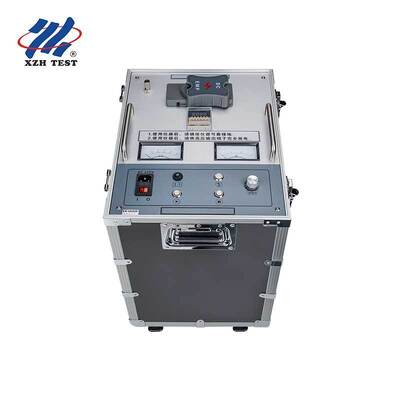
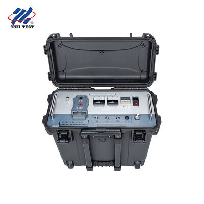
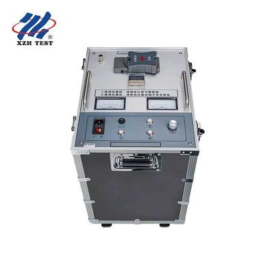
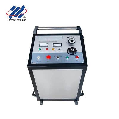
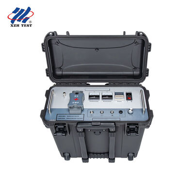
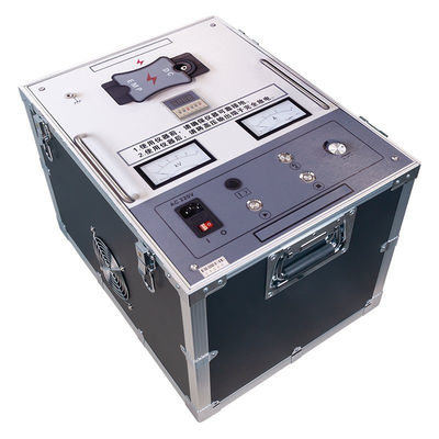
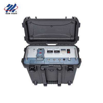
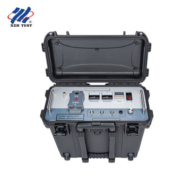
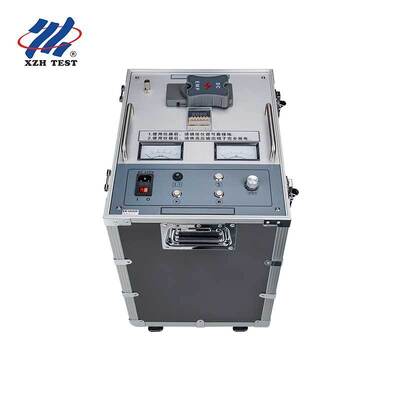
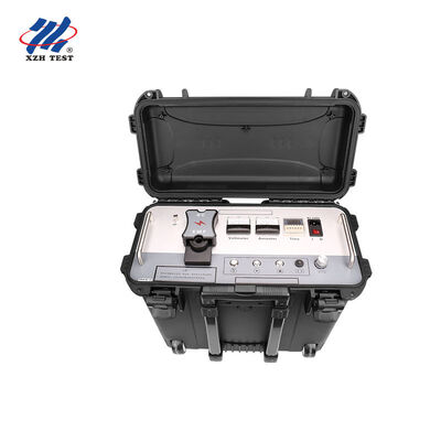
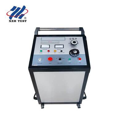
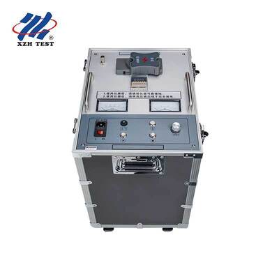
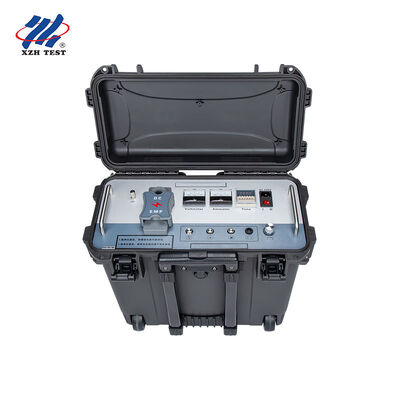
The XHHV535-2L is built for professional cable fault location teams who need 35kV-class impulse discharge capability without the logistics of a trolley-mounted unit. Its pull-rod chassis delivers the same high-voltage performance as bulkier cart-type generators while enabling single-operator deployment in locations with restricted access — substations with stair-only access, cable trenches with narrow approach paths, and multi-story industrial facilities where elevator dimensions limit equipment size.
The defining engineering achievement of the XHHV535-2L is delivering full 35kV impulse discharge capability in a pull-rod portable chassis. Conventionally, 35kV-class surge generators require trolley-mounted enclosures with substantial clearance distances, heavy-gauge internal wiring, and oversized capacitor banks — all of which drive weight and bulk. The XHHV535-2L achieves the same voltage rating through high-frequency solid-state HV technology, miniaturized high-reliability circuit design, and an integrated charging/discharging architecture that eliminates external interconnecting HV cabling and separate capacitor modules.
Operational Impact: A 35kV-capable surge generator that one technician can carry from the vehicle to the test point — through gates, up stairs, across cable trenches — is a significant operational advantage for field service organizations. It reduces vehicle requirements (no lift-gate needed), speeds up per-job deployment time, and eliminates the scheduling constraint of needing two-person crews for routine 35kV fault callouts.
| Safety Feature | How It Protects |
|---|---|
| Zero-Position Start Interlock | Voltage adjustment knob must be at zero before HV output can be enabled — prevents accidental 35kV startup at full voltage |
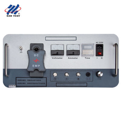
| Real-Time Standby Voltmeter | kV meter displays capacitor voltage continuously — even when the instrument is stopped. Operator always knows energy state before approaching terminals |
| Triple Auto Protection | Independent overcurrent, overvoltage, and overheat circuits monitor output simultaneously — automatic trip on any fault condition |
| Direct Short-Circuit Tolerance | Output stage engineered to survive dead-short conditions during aggressive fault conditioning — no damage, no fuse replacement, just reset and continue |
| Manual Discharge Capability | Controlled dissipation of residual capacitor energy via operator command — secondary safety layer beyond automatic discharge circuit |
| Configurable Discharge Timing | Arbitrarily settable discharge intervals — operator controls impulse cadence for optimal acoustic pinpointing without rushing or over-cycling |
The XHHV535-2L integrates a charging circuit and a discharging circuit within a single compact enclosure. The charging circuit samples HV cable voltage and routes it to a voltage regulation control loop — ensuring the 2μF energy storage capacitor charges precisely to the operator-selected level (0-35kV). The discharging circuit, triggered by the impulse mechanism, transfers stored energy through a precision-gapped high-voltage discharge sphere to the output terminal — generating a fast-rising DC impulse pulse that produces both the acoustic thump and electromagnetic transient required for TDR pre-location and acoustic-magnetic pinpointing.
The impulse magnet — an integrated assembly housing the DC high-voltage power supply, energy storage capacitor, and discharge sphere in a single modular unit — is the key to the XHHV535-2L’s compact form factor. By eliminating the interconnecting cables, separate capacitor banks, and external sphere gaps of traditional component-level setups, the impulse magnet achieves the same electrical performance in a fraction of the physical volume.
| Application | Target Cable Type |
|---|---|
| Cable Fault Pinpointing | 35kV and below XLPE, PILC, and EPR insulated power cables — urban distribution, industrial feeders, and renewable energy collector circuits |
| DC Withstand Voltage Testing | Post-installation and post-repair insulation verification on 35kV cables and electrical equipment including transformers and switchgear |
| High-Voltage Flashover Testing | Controlled flashover induction for TDR waveform acquisition and fault pre-location distance measurement |
| Acoustic-Magnetic Synchronization | Synchronized impulse discharge for precise fault point location using external acoustic and magnetic field receivers |
| Preventive Maintenance Assessment | Scheduled cable condition evaluation — impulse response baseline trending for early detection of insulation deterioration in aging 35kV networks |
Q: How does a high voltage surge generator work in cable fault detection?
The surge generator discharges a high-energy pulse into the faulty cable, creating a controlled high-voltage arc at the fault point. This arc produces both an acoustic signal (loud thumping sound detectable by ground microphones) and an electromagnetic pulse (detectable by an inductive receiver). By combining acoustic and electromagnetic signal arrival times, operators can pinpoint the exact fault location with precision—a technique known as acoustic-magnetic synchronization.
Q: Which voltage range should I select for different cable types?
Voltage selection follows the cable's rated operating voltage as a general guideline. For low-voltage cables (up to 1kV), use the 8kV or 12kV range. For medium-voltage distribution cables (6-15kV), the 16kV range is appropriate. For high-voltage transmission cables (35kV and above), use the 32kV range. Always consult the cable manufacturer's maximum test voltage specifications and ensure all safety clearances are maintained during high-voltage operation.
Q: What safety precautions must be observed during surge generator operation?
High voltage surge generator testing requires strict safety protocols. Always verify the cable is fully de-energized and isolated from all power sources before connection. Establish a minimum 5-meter safety perimeter around the test zone with warning signs. All personnel must wear appropriate PPE including arc-rated clothing, HV insulating gloves, and dielectric overshoes. The integrated safety features—automatic discharge upon power-off, emergency stop, and zero-voltage interlock—provide additional layers of protection but should never replace proper safety procedures.
Q: What is the advantage of multiple energy levels (Joules) on this unit?
Different energy levels serve different diagnostic purposes. Low energy settings (e.g., 864J–1024J) are ideal for initial fault confirmation and locating high-resistance faults where excessive energy could worsen cable damage. Medium energy (1225J–2048J) provides optimal acoustic signal strength for most routine fault pinpointing. High energy (2450J+) is reserved for very long cables, deep burial scenarios, or high-impedance faults that require stronger arc generation to produce a detectable acoustic signature. The three-level selection allows operators to match energy output to field conditions.
Q: What warranty and support is included with this surge generator?
12-month standard warranty against manufacturing defects with lifetime technical support. CE and ISO 9001:2015 certified. Each unit includes the surge generator, HV output cable, ground cable, discharge rod, user manual, and a heavy-duty trolley with locking casters for safe transport. On-site installation, commissioning, and operator safety training are available upon request. Spare parts including discharge gaps, capacitors, and HV diodes are stocked for rapid replacement.
Overall Rating
Rating Snapshot
The following is the distribution of all ratingsAll Reviews