XHSB505B
This cable identifier is based on the on-site identification of multiple cables urgently needed by high-voltage cable construction, installation and maintenance personnel, referring to foreign advanced technology, and under the guidance of electromagnetic field theory, it is developed by using modern electronic technology and tooling technology.
A very difficult question is often encountered in field operations such as power cable laying, migration, maintenance, troubleshooting: which cable are we looking for? Especially in many cable channels with the same specification, the construction workers are at a loss what to do. This device can help you solve this problem quickly and accurately.
Working principle
Non-charged cable detection: The transmitter mainly generates a special pulse signal, which is added to the cable to be identified through the connecting line. According to the principle of electromagnetic induction, an induction signal consistent with the law of the transmitted signal must be generated along the cable. It is used in the test site. The high-sensitivity receiving clamp plus the handheld receiver detects all the cables on site, and the cable to which the signal is added can be accurately found out according to the indication of the handheld receiver meter (that is, the uncharged cable to be identified).Live cable detection: The transmitter mainly generates a special pulse signal, which is added to a point of the live cable to be identified through a special transmitting clamp. According to the principle of electromagnetic induction, an induction signal consistent with the law of the transmitted signal must be generated along the cable. During the test Use highly sensitive receiving pliers and a handheld receiver to detect all the cables on the site, and you can accurately find out the cable with the added signal (that is, the live cable to be identified) according to the instructions of the handheld receiver.
Features
The recognition is accurate.
Large identification jaws fit a wide variety of cables.
very easy to operate.
Instructions are clear and intuitive.
The main and auxiliary parts are portable and beautiful.
The receiving signal strength of the receiver is adjustable.
Both live and dead cables can be tested.
Small and portable, light weight.
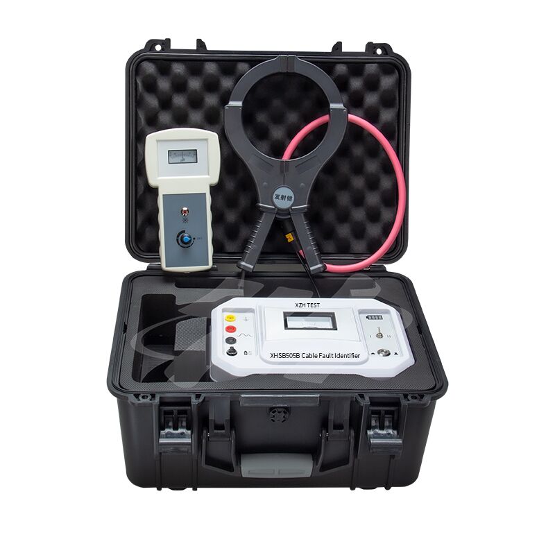
This instrument consists of a transmitter, a transmitting clamp, a receiving clamp, a handheld receiver, etc.
Transmitter panel:

1. Grounding pole: equipment safety grounding terminal;
2. Output positive pole: transmitter output positive, connect the red output line;
3. Output negative pole: transmitter output negative, connect the black output line;
4. Charging: DC12V charging port, connect the 12V charger to start charging;
5. Power switch: turn on/off the working power;
6. Gear switch: "Ⅰ" for non-powered cable identification; "Ⅱ" for powered cable identification;
7. Power indicator: real-time indication of battery power when the built-in battery is working;
8. Ammeter: displays the instantaneous average value of the output current.
1. The handheld receiver has an adjustment knob that can adjust the received signal strength (clockwise rotation: the received signal strength increases; counterclockwise rotation: the received signal strength decreases; and it has a switch function).
2. There is a BNC interface on the lower side of the handheld receiver, which is connected to the receiving clamp to receive the signal when used.
Technical Parameters
| Identification method |
Judging by the direction in which the pointer swing; |
| Jaw size(diameter) |
Transmitter clamp: Φ125mm;
Receiver clamp: Φ200mm;
|
| Output voltage |
I gear (direct connection method): 150V, II gear (coupling method): 250V; |
| Test range |
Direct connection method: 0Ω~1k
Coupling method: 0Ω~50Ω;
|
| Pulse current |
0~10A; |
| Pulse cycle |
2.75S/time; |
| Power supply |
12VDC lithium battery for the transmitter, AA battery for the handheld receiver. |
Instructions for identification of non-charged cables - direct connection method
1. Disconnect the armor at both ends of the cable from the ground, clamp the red clip of the output wire of the transmitter on the core wire of the cable to be tested (good phase or phase with higher insulation), and clamp the black clip of the output wire of the transmitter on the core wire of the cable to be tested. On the ground point or ground stake, the corresponding core wire of the cable is connected to the ground point or ground stake at the far end, as shown in the figure above.
2. Turn on the power switch of the main body of the transmitter, select the "Ⅰ" position of the gear switch, the power switch light flashes three times, and the pointer of the ammeter also swings three times at the same frequency, and the pulse signal is output cyclically in turn.
3. Connect the receiver to the receiving clamp, and the receiving clamp is clamped on the cable to be tested.
4. Note that the direction of the arrow of the receiving clamp is the direction of current inflow (positive direction), otherwise the swing of the watch hand is just the opposite.
5. Turn the receiver adjustment knob clockwise, and when you hear a "beep", turn on the receiver switch. Then adjust the receiving signal strength of the receiver to an appropriate position. At this time, only the signal can be received on the cable that adds the signal, and the signal swing frequency is consistent with the transmitter frequency, and a "di-di-di" sound is issued.
Live Cable Identification Instructions - Coupling Method
Coupling method notes:
1. No need to do any operation on the cable under test, just clamp the launch clamp on the cable for testing.
2. Both ends of the cable sheath must be well grounded, otherwise the coupling current will decrease with the increase of the grounding resistance.
3. If the sheath at both ends is not grounded or the middle of the sheath is disconnected, the coupling method cannot be used.
4. When the launching pliers are inserted into the cable, the direction of the arrow on the pliers points to the end of the cable.
5. Keep the receiving clamp and transmitting clamp at a distance of 2 meters as much as possible.
Method:
1). Connect the output end of the transmitter to the launch clamp, and clamp the launch clamp to the proper position of the live cable to be identified, as shown in the figure above.
2). Turn on the power switch of the main unit of the transmitter and select the "II" position switch. The power switch light flashes three times, and the pointer of the ammeter also swings three times at the same frequency, and the pulse signal is output cyclically in turn.
3). Connect the receiver to the receiving clamp, and the receiving clamp is clamped on the cable to be tested.
4). Note that the direction of the arrow of the receiving clamp is the direction of current inflow (positive direction), otherwise the hands of the watch will swing in the opposite direction.
5). Turn the receiver adjustment knob clockwise, and when you hear a "beep", turn on the receiver switch. Then adjust the receiving signal strength of the receiver to a suitable position. At this time, only the signal can be received on the cable that adds the signal, and the signal swing frequency is consistent with the output switching frequency of the transmitter, and the sound of "di-di-di" will be issued.
Packing List
| Transmitter |
1 |
| Receiver |
1 |
| Charger |
1 |
| Output line-red |
1 |
| Output line-black |
1 |
| Transmitting clamp |
1 |
| Receiving clamp |
1 |
| 5AA battery |
2 |

 Your message must be between 20-3,000 characters!
 english
 français
 Deutsch
 Italiano
 Русский
 Español
 português
 Nederlandse
 ελληνικά
 日本語
日本語
 한국
한국
 العربية
 हिन्दी
 Türkçe
 indonesia
 tiếng Việt
 ไทย
ไทย
 বাংলা
বাংলা
 فارسی
فارسی
 polski