XZH TEST 32kv Low Medium Voltage Cable Fault Pinpointer High Voltage Underground Cable Fault Locator
Product Features
- 10.1-inch full-color TFT touch screen;
- Embedded system, safe, stable, simple display and operation mode;
- With the function of testing cable wave velocity, cable length and fault distance;
- Fully automatic continuous sampling, waveform capture at all times, timely and accurate.
- With automatic test range setting, automatic waveform analysis and display of test distance.
- Full Chinese menu, touch and coding button two operation modes, simple, fast and reliable.
- With low-voltage pulse method, high-voltage flashover method, multiple pulse method (8 times) test technology, waveform display is smooth and easy to read.
- When using the multiple pulse method, it is used with a pulse coupler to display 8 groups of high and low voltage waveform comparisons, which is convenient for automatic test distance, manual analysis and distance measurement.
- The instrument has powerful data processing capabilities, which is convenient for users to manage and archive waveform files.
- It has a massive test waveform storage function: the waveforms tested on site can be conveniently stored in the instrument in the order specified by the Chinese naming regulations, so that they can be called up for observation and analysis at any time; it can store more than 8,000 low-voltage pulse and high-voltage flashover waveform records, and more than 250 multiple pulse waveform records. The waveform files can be imported into the computer software for management and analysis using USB communication.
- Ultra-high brightness, LED backlight brightness up to 280nit, resolution 1024*600, easy to operate in direct sunlight.
- Built-in large-capacity lithium battery pack, supports fast charging, and can be tested in an environment without power supply.
General features |
| Portable cable fault location system |
| Graphical interface |
Graphical interface, more intuitive and easy to operate. |
| Operation |
Turn and click a single knob (jog dial) on the control unit |
| Data management |
General database |
| Data Synchronization |
Universal Serial Bus |
Control unit |
| Display |
Industrial grade TFT color panel with LED backlight |
| Anti-glare |
have |
| Multi-touch |
have |
| LCD size |
10" |
| Aspect Ratio |
16:9 |
| Resolution |
1024 x 768 Full HD |
| Brightness |
450 cd/m² |
Safety |
| Adaptability |
CE Compliance;EN 61010,EN 50191,VDE 0104,VDE 015,DGUV 203-034(BGI 891) |
| Discharge and grounding devices |
72kJ, equivalent to the energy stored in a 10µF capacitor charged to 120kV DC fast charge: discharge time constant < 1 second |
| System Status |
Real-time monitoring and indication |
| Intrinsically safe |
Ground immediately when there is a power outage |
| F-U safety interlock |
Operating voltage connection monitoring (high voltage circuit) |
| F-Ohm Safety Interlock |
Operational earth connection monitoring (high voltage circuit) |
| Security Features |
Front panel: power on/off, lockout button switch, emergency stop, residual pressure indicator light, high voltage switch; Control unit: Knob (jog dial) |
| Safety devices |
System grounding status indicator, power input protection device, high voltage room monitoring through door contact, external safety device |
| Power input monitoring |
Overvoltage protection, undervoltage protection, residual current device (RCD) |
| Defining Wiring |
There is a switchboard inside the system |
System function |
|
1.Use DC or high-voltage pulse to make the cable fault point flash over and discharge
2.Use the traveling wave reflection principle to make a rough measurement of all types of cable main insulation faults
|
I,High voltage surge generator |
| Output mode |
DC, Single, Cycle |
| Output voltage |
8kV,16kV,32kV |
| Built-in capacitor |
64uF,16uF,4uF |
| Discharge energy |
2048J @ each voltage level |
| Impact power |
2000VA |
| Impulse rate |
Automatic impact for about 6 seconds, manual impact for any control time |
| Surge voltage levels switch |
Manual |
| Voltage adjustment type |
Continuous |
| Indication |
High-voltage side voltage metering, indication of output voltage and current in real time |
| Operating modes switch |
Manual |
| Coupler |
Built-in multiple pulse sampling box |
| Safe protection |
With zero start protection function, safe and reliable |
| Discharge |
Unique high-voltage measurement design, in the stop state, it will automatically discharge the internal capacitance of the device |
| Working power |
AC 220V±15% ,50Hz±2Hz(60Hz) |
| DC withstand voltage testing |
Output voltage adjustable and indication range 0-32kV, output current indication range 0-20A |
| Burn current |
Fault conditioning (burning) with current up to
60 mA @ 32 kV, 120 mA @ 16kV, 240mA@8kV
|
| Safety |
Over-voltage, Over-current, Overheating protection.
Automatic discharge after operation
|
| Protection rating |
Not lower than IP54 |
| Dimensions(mm) |
534L*444W*805H mm |
| Total weight |
Not more than 130kg |
II,TDR cable fault locator |
| Test method |
Low voltage pulse, Impulse current, Impulse voltage, ARC multipls pulse |
| Sampling rate |
1MHz~400MHz |
| Pulse output |
Unipolar |
| Pulse Amplitude |
300V |
| Pulse width |
0.15μS/0.30μS /0.60μS/1.20μS/2.4μS/5.0μS/7.5μS/10μS |
| Measurement scope |
≥120km |
| Measurement range |
100m/300m/500m/1km/3km/5km/10km/25km/50km/100km |
| Minimum resolution |
0.07m |
| Measurement error |
≤±(0.5%*L+1m),L is cable length |
| Signal gain |
0…100%,adjustable |
| Propagation speed |
10…999.9m/µs |
| Output Impedance |
Automatic match |
| Trigger |
Automatic continute
|
| Result analysis |
Automatic measure fault distance |
| Working conditions |
temperature -25℃~+65℃, relative humidity 85%, atmospheric pressure 750±30mmHg |
V Test cables |
| (Note: Due to the existence of 35kV high voltage, special high voltage cables are made and should be kept away from the site during operation.) |
| High voltage output cable |
core wire 2.5mm2 red, withstand voltage 50kV DC, with shielding layer, outer diameter 14mm, length can be customized according to customer’s requirements, including installation of large spool. |
| Ground cable |
grounding 3-column - main core 16mm2 transparent color, branch 2.5mm2, length can be customized according to customer’s requirements, including installation of small spool. |
Equipment Testing

This device can use the multiple pulse method to measure distance, and only one short-circuit wire is needed. In addition, when accurately locating the cable fault, it can also be switched to the high-voltage flash-over method (pulse current method - ICE), just remove the short-circuit wire and insert the high-voltage output cable into another HV output port. This ensures high energy output during accurate locating, and will not reduce part of the energy due to the multiple pulse coupler, resulting in less clear sound when listening to the fault discharge sound.
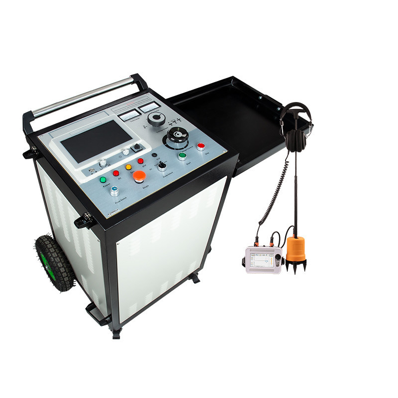
Cable fault pinpointer MODEL XHDD503C
Packing list
Instrument composition
- Cable fault test system: Use low-voltage pulse method, high-voltage flashover method, and multiple pulse method to test and analyze cables and apply high voltage and high-energy pulse signals to the tested cables;
- Output line (5-meter single Q line): Connect the cable fault tester and the tested cable during low-voltage pulse test;
- Charger: 12.6V/3A charger, connected to the instrument charging port for charging;
- USB cable: used when importing waveform files to the computer.
- High-voltage output line (5 meters): connect the high-voltage output terminal of the host and the cable core under test;
- High-voltage connecting line (0.5 meters): short-circuit the high-voltage flashover output terminal and the multiple pulse input terminal during the multiple pulse method test;
- Ground line (5 meters): sampling ground, high-voltage ground and discharge rod ground line;
- Power line (1.8 meters): instrument working power line;
- Discharge rod: perform DC current limiting discharge or DC short-circuit discharge at the cable end under test;
- Fuse: AC220V power supply system spare fuse (8A fuse).
Panel introduction
- 1 Switch: Turn on/off the working power;
- 2 Amplitude: When collecting waveforms, adjust the amplitude knob to change the amplitude of the collected waveform.
- 3 Display: 10.1-inch full-color TFT touch screen.
- 4 Operation knob: Rotary button for system interface operation control, rotate to select and press to confirm;
- 5 Mode selection: Low Voltage Pulse: Low voltage pulse method; HV Flash: High voltage flashover method; Multiple Pulse: Multiple pulse method;
- 6 Voltmeter: High voltage output voltage indication kV meter, divided into 8kV, 16kV, 32kV combined with voltage level switch reading.
- 7 Ammeter: Indication of current size.
- 8 Voltage rotation mode (Voltage select): This key has three voltage level modes, 8kV, 16kV, 32kV. Please rotate to the appropriate position before turning on the machine. Lift, rotate, and press.
- 9 Voltage control knob: When this knob is in the zero position, the zero position light is on and the high voltage can be started. The voltage can be increased only after the high voltage is started.
- 10 Stop button: When the test is completed or an abnormality occurs, press this button to cut off the high voltage output, and the remaining high voltage of the test will be automatically discharged.
- 11 Start button: In the zero position, press the start button, the high voltage starts, and the high voltage light is on. In the non-zero position, the high voltage light is not on.
- 12 Overcurrent protection switch (OCP): When pressed, the overcurrent protection function has started; when it pops up, it means that the instrument has triggered the overcurrent protection.
- 13 Mode select: It is divided into three modes: withstand voltage (DC), single, and cycle. DC is the withstand voltage function. When this function is selected, the cable will be subjected to withstand voltage test; Single is a manual function. When this function is selected, the high voltage will be started and then boosted. Pressing the Single key can manually trigger the impact discharge; Cycle is an automatic function. When this function is selected, the high voltage will be started and boosted. The instrument will automatically trigger the impact discharge for about 7 seconds.
- 14 Overheat indication (OTP): When performing multiple pulse method tests, this light will light up, indicating that the internal temperature of the instrument is too high. Please stop using the multiple pulse method test.
- 15 Single key (Single): When the mode selection key is in the Single function, this key is valid.
- 16 Power switch (Power Switch): Turn clockwise to turn on the system power supply, and counterclockwise to turn off the system power supply.
- 17 Zero position light (Zero): Indicates that the voltage adjustment knob is in the zero position state. The high voltage can only be started when the zero position light is on.
- 18 Power light (Power): When the power switch is turned on, the indicator light is on.
- 19 High-voltage light (HV): When it is on, it indicates high-voltage output; when it is off, it indicates no high-voltage output.
1 Power socket (220V 50Hz): instrument working power supply, AC220V connection port. (connect when using high-voltage pulse generator);
2 Fuse holder: AC220V power supply system fuse installation place;
3 Communication socket (Signal): use a single Q line to connect the machine and the cable under test to collect waveforms, which is only valid when low-voltage pulses are used.
4 USB: use USB communication to import waveform files into the computer;
5 Charging: DC12.6V charging port, connect a 12.6V charger to start charging.
1 Sampling ground: The negative end of the pulse energy storage capacitor has a high voltage and must be reliably grounded. It is used for sampling when sampling waveforms in the high-voltage flashover state of the cable fault tester. (Reliable grounding is still required for sampling without high-voltage flashover).
2 High-voltage ground: Also known as the high-voltage tail, it must be reliably grounded to prevent high-voltage leakage and discharge. Poor contact may result in failure to boost the voltage, high-voltage breakdown and damage to the internal components of the instrument, and internal leakage or discharge of the instrument causing safety accidents.
3 High-voltage flashover output (HV Flash OUT): Dedicated DC high-voltage output terminal.
4 Multiple pulses (Multiple Pulse input, output): When using the multiple pulse method, the high-voltage flashover output terminal and the multiple pulse input terminal are short-circuited with a high-voltage connection line, and the high-voltage output line is connected to the multiple pulse output terminal.

 Your message must be between 20-3,000 characters!
 english
 français
 Deutsch
 Italiano
 Русский
 Español
 português
 Nederlandse
 ελληνικά
 日本語
日本語
 한국
한국
 العربية
 हिन्दी
 Türkçe
 indonesia
 tiếng Việt
 ไทย
ไทย
 বাংলা
বাংলা
 فارسی
فارسی
 polski