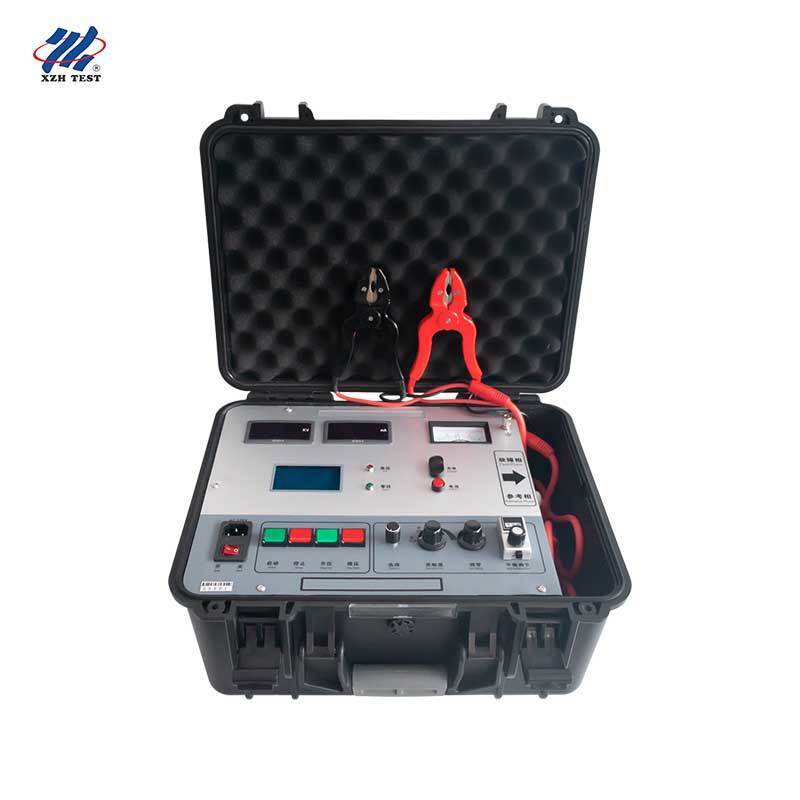
Cable Sheath Fault Locator | XHHG521B
The XHHG521B cable sheath fault locator is a high-voltage bridge cable fault tester designed based on the principle of the Murray bridge. It can be used to locate the breakdown points of various wires and cables after laying, as well as defect points that have not broken down but show low insulation resistance. It can also be used to locate defective points of various cables in the cable factory, making it an essential tool for cable maintenance and repair.
The device uses an electric voltage regulator and an R-type transformer to form a high-voltage constant current source, with keypad control for raising and lowering the voltage. With an open-circuit voltage of 5600V and a short-circuit current of 100mA, it uses a high-sensitivity amplifier and galvanometer for balance indication, forming a balanced bridge with the ratio potentiometer, all placed at high potential. The measuring cable is a specially designed double-core high-voltage rubber cable, and the four-terminal resistance measurement method avoids errors introduced by lead resistance. The panel is entirely at low potential for operator safety.
The instrument is equipped with an LCD display and one-key operation: input the cable length and the fault distance is calculated automatically. The high-voltage source and the bridge are integrated in one portable protective case, giving the device high voltage, light weight, convenient operation and safe use.
Applications & Target Audience: Engineered for electric power research institutes and provincial electric power academies, electrical test laboratories of large industrial enterprises performing preventive tests, electrical maintenance departments of thermal, nuclear and hydro power plants, overseas power equipment agents and distributors, power supply branches of urban rail transit operating companies, and cable maintenance departments of municipal public utilities such as water and gas groups.
Key Specifications
| Parameter |
Specification |
| Open-circuit Voltage |
≥ 5600V |
| Short-circuit Current |
≥ 100mA (5 ~ 40mA recommended when balancing) |
| Location Accuracy |
±(0.2%·L ± 1) m |
| Weight |
25 kg |
| Working Power |
AC 220V (±10%), 50Hz ±1Hz; built-in 8.4V battery |
| Measurement Principle |
Murray bridge (balanced bridge method) |
| Display |
LCD display, one-key operation, automatic fault distance calculation |
Product Features
Adjustable output voltage with high accuracy and stability
High-sensitivity amplifier and galvanometer for precise balance indication
Zero-position protection: the instrument cannot start unless the voltage is at zero
Automatic fault point testing with manual testing function retained
Compared with the wave reflection method, the bridge balance method has no blind zone, and is used to judge breakdown points of short cables and points close to the cable end
Four-terminal resistance measurement avoids lead resistance errors; double-core high-voltage rubber measuring cable supplied

Three Fault Types the XHHG521B Excels At
The XHHG521B is especially suitable for three types of cable faults that are difficult for other methods to handle reliably.
| Fault Type |
Description |
Why the XHHG521B Works |
| Linear high-resistance breakdown |
High-resistance breakdown points after cable laying, especially those difficult to burn into low resistance, such as linear high-resistance breakdown of cable middle joints |
The constant current source applies 5600V to break down the point; the bridge measures the ratio accurately without needing a low-resistance fault |
| Flashover-type breakdown |
Points that break down only under voltage and extinguish when voltage is removed |
After breakdown, the constant current source maintains the arc, so a stable current flows through the bridge and the galvanometer has enough sensitivity to balance |
| Low-resistance defect points |
Points not broken down but with low insulation resistance, e.g. found by megohmmeter but not breaking down at operating voltage |
The bridge method measures the resistance ratio directly, locating the defect before it develops into a full breakdown |
Working Principle
The cable fault location bridge method works as follows: short-circuit the faulty phase of the tested cable with a healthy phase, connect the two arms of the bridge to the faulty phase and the healthy phase respectively, and adjust the adjustable resistor on one arm of the bridge until the bridge is balanced. Using the ratio relationship and the known cable length, the fault distance can be obtained.
If the distances from the two ends of the tested cable to the breakdown point are L1 and L2, the total cable length is L, and the corresponding core resistances are R1 and R2, then after the bridge is balanced, the reading P (in percent) directly gives the fault position: L1 = P% · L. The Murray bridge method for breakdown point location is a classic approach that is convenient and accurate. Its basis is that the core (or shield) resistance is uniform and proportional to the length. The bridge method is relatively simple and its accuracy meets field engineering test requirements, making it especially convenient for two-phase short-circuit faults of cable lines.
Measurement Procedure
Preparation
Use a multimeter, megohmmeter or other withstand voltage equipment to confirm the cable breakdown state and record the insulation resistance or breakdown residual voltage of each core
Record the cable length, model and cross-section; walk along the cable route, short-circuit the outlet terminals of the faulty cable and the auxiliary cable at the far end, and leave a person at the far end to guard against high-voltage injury
Connect the instrument ground terminal reliably to the site grounding body; connect the red measuring clip to the faulty cable core and the black clip to the auxiliary cable core
Measurement
Connect AC 220V power, turn on the sensitivity switch and rotate it to maximum; the battery indicator lights up
Zero the bridge: rotate the zero adjustment knob until the galvanometer points to zero
Raise the voltage: turn on the power switch, confirm the zero-position light is on, press the start button, and the high-voltage indicator lights up
Press the raise button and watch the voltmeter and ammeter until the current exceeds 20mA; if the current is unstable, continue raising the voltage and hold it to form a stable arc or conductive zone
Balance adjustment: rotate the balance knob until the galvanometer points to zero, then record the reading P1 and stop raising the voltage
Calculation
Input the cable length on the LCD page using the encoder switch: rotate to move the cursor, press to confirm each digit
On the test page, move the cursor to Test and press the encoder switch; the system automatically collects the bridge ratio coefficient P once and calculates the fault distance X
Verify by reversing the clips and repeating the measurement to obtain P2; the sum P1 + P2 should equal 100, confirming the result
Calculation & Verification Formulas
When the auxiliary cable has the same cross-section as the faulty cable, the fault position is X = 2 × L × P1%. Pay special attention to the factor "2", because connecting the auxiliary cable doubles the cable length participating in the calculation.
When the auxiliary cable has a different cross-section, convert it to the faulty cable length: if the fault cross-section is Sx and the auxiliary cable cross-section is S, then X = P1% × (1 + Sx/S) × L.
If all three cores of a three-core cable are broken down or short-circuited to each other, select the core with the best insulation resistance as the auxiliary cable. For the reverse-connection check, lower the voltage, discharge, swap the measuring clips, repeat the measurement to get P2, and verify P1 + P2 = 100.
Panel Layout
| Panel Element |
Function |
| Galvanometer |
Electrical balance zero point adjustable |
| Ammeter |
Output current indication in mA |
| Voltmeter |
High-voltage output indication in kV |
| High-voltage indicator light |
Lights up when high voltage is output |
| LCD display |
Shows operation content and fault distance |
| Zero-position indicator light |
Lights up when voltage output is at zero position |
| Power socket & fuse holder |
AC 220V connection and fuse installation |
| Power switch |
"I" gear turns on AC 220V, "0" gear turns off |
| Start button |
Valid only when the zero-position light is on; starts high-voltage output |
| Stop button |
Cuts off high-voltage output when test is completed or abnormal |
| Raise / lower buttons |
Increase or decrease the output high voltage |
| Select encoder switch |
Rotate to move cursor or modify digits; press to execute or confirm |
| Sensitivity adjustment |
Built-in battery power switch and sensitivity adjustment with zero knob |
| Zero adjustment knob |
Rotate to make the galvanometer point to zero |
| Balance adjustment |
Rotate to make the galvanometer point to zero and read the ratio P1 |
| Battery indicator |
Lights up when the built-in battery is working |
| Reference terminal |
Connects the reference phase (black clip) |
| Fault terminal |
Connects the faulty phase (red clip) |
| Charging port |
DC 8.4V charging port for the built-in battery |
| Ground terminal |
Instrument grounding point for safety protection |
Notes & Safety
Never turn on the instrument while connecting cables; turn off the power after the test
The instrument cannot start when the voltage adjustment is not at zero position
At least two persons must be present; one connects the wiring and the other checks it before starting the test
The instrument ground must be reliable, using the dedicated ground wire, preferably connected to the site ground column, electrical cabinet ground bar or equipment base
During and after the test, discharge before touching high-voltage parts, and finally hang the ground wire
Automatic fault distance calculation must be performed in the non-boosted state
If interference affects the galvanometer zero point, re-zero at the final sensitivity position for a more accurate reading
FAQ
Q1: What is the XHHG521B cable sheath fault locator used for?
It is used to locate breakdown points of wires and cables after laying, defect points with low insulation resistance but no breakdown, and defective points of cables in cable factories, based on the Murray bridge principle. It is an essential tool for cable maintenance and repair.
Q2: What is the Murray bridge principle?
The faulty phase of the tested cable is short-circuited with a healthy phase, the two arms of the bridge are connected to the faulty and healthy phases, and the adjustable resistor is adjusted until the bridge is balanced. The ratio relationship and the known cable length then give the fault distance: L1 = P% · L.
Q3: What faults is it especially suitable for?
Three types: linear high-resistance breakdown points that are difficult to burn into low resistance, such as middle joint breakdowns; flashover-type breakdown points where the constant current source maintains the arc; and low-resistance defect points found by megohmmeter that do not break down at operating voltage.
Q4: What are the key technical specifications?
Open-circuit voltage is at least 5600V, short-circuit current at least 100mA (5~40mA recommended when balancing), location accuracy is ±(0.2%·L ± 1) m, weight is 25kg, and the working power is AC 220V with a built-in 8.4V battery.
Q5: Why choose the bridge method over the wave reflection method?
The bridge balance method has no blind zone, making it especially suitable for judging breakdown points of short cables and points close to the cable end, where wave reflection methods have difficulty. It is convenient, accurate and meets field engineering test requirements.
Every XHHG521B is delivered with the host, a high-power jumper cable set, a power cord, a ground wire, a charger and 5 spare fuses (3A), and is backed by one-year free warranty and lifetime maintenance and technical service. For ordering, training and after-sales support, please contact our sales team.


 Your message must be between 20-3,000 characters!
 english
 français
 Deutsch
 Italiano
 Русский
 Español
 português
 Nederlandse
 ελληνικά
 日本語
日本語
 한국
한국
 العربية
 हिन्दी
 Türkçe
 indonesia
 tiếng Việt
 ไทย
ไทย
 বাংলা
বাংলা
 فارسی
فارسی
 polski