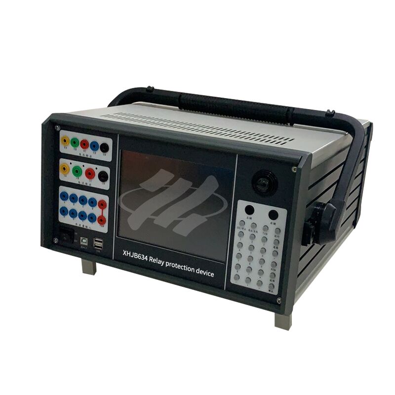
XHJB634 Microcomputer Relay Protection Calibrator is a compact microcomputer-based relay protection testing instrument adopting microelectronic technology. Complying with DL/T624-2010 standard for microcomputer relay protection test devices, it is upgraded by analyzing the pros and cons of conventional similar products.
Built-in high-performance industrial PC and high-speed DSP, matched with 16-bit DAC module, 8.4-inch LCD screen and embedded keyboard. The device is operable either independently or with a laptop connection, boasting robust functions, small footprint and superior precision.

Technical Parameters
★ AC Current Source: Single Phase: 3×40A Three Phase: 120A Power: ≥450VA/phase
★ Output Time: 0~10A Continuous, 10~20A ≥60 seconds, >20A ≥10 seconds
★ AC Voltage Source: Single Phase: 4×120V Power: ≥60VA/phase
★ DC Current Source: Single Phase: -10A~+10A Maximum Output Power: ≥200VA
★ DC Voltage Source: Single Phase: -150V~+150V Maximum Output Power: ≥100VA
★ AC Source Angle: Phase Angle: 0°~360° Accuracy: ±0.2°
★ AC Source Frequency: Frequency: 1~2000Hz Frequency Resolution: 1mHz
★ Harmonic Output: Capable of outputting harmonics of any amplitude from the 2nd to the 40th order
★ Synchronization: Voltage and current synchronization ≤10μS
★ Input: 8 channels compatible with 15V~250V active contacts, automatically identifies active contact polarity
★ Timing accuracy: ≤1ms when less than 1s
★ Output: 4 pairs of programmable switch dry contacts, capacity: AC/DC 250V, 0.5A
★ Power supply: 220V±10% 50Hz±10%
During testing, the voltage is tested point by point within this range. The frequency varies in each test round, but the voltage remains constant at a certain value. The voltage value gradually increases from the initial value until a certain value is reached, at which point the device releases the lockout and operates correctly. This value is the low-voltage lockout boundary value.
Since the device is locked when the voltage is below the lockout value, the initial change value should generally be set below the device's set lockout value, and the final change value should be set above the device's set lockout value. In other words, the test proceeds from the device not operating to operating, thereby measuring the device's low-voltage lockout value.

 Your message must be between 20-3,000 characters!
 english
 français
 Deutsch
 Italiano
 Русский
 Español
 português
 Nederlandse
 ελληνικά
 日本語
日本語
 한국
한국
 العربية
 हिन्दी
 Türkçe
 indonesia
 tiếng Việt
 ไทย
ไทย
 বাংলা
বাংলা
 فارسی
فارسی
 polski
Overall Rating
Rating Snapshot
The following is the distribution of all ratingsAll Reviews