logo
Home > Products >
Cable Fault Locator
>
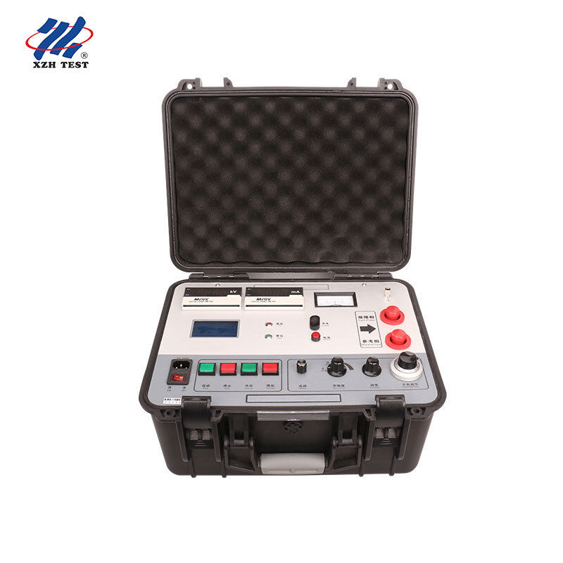
Murray Bridge Cable Sheath Fault Pre-Locator XHHG521A 7500V High Precision No Blind Area for Short Cable Testing

Murray Bridge Cable Sheath Fault Pre-Locator XHHG521A 7500V High Precision No Blind Area for Short Cable Testing

Product Details:
Place of Origin: Xi'an ,Shaanxi,China
Brand Name: XZH TEST
Certification: CE ISO
Model Number: XHHG521A
Detail Information
Place of Origin:
Xi'an ,Shaanxi,China
Brand Name:
XZH TEST
Certification:
CE ISO
Model Number:
XHHG521A
N.W:
25kg
No Load Voltage:
7500V
Highlight:

High Light

Highlight:

Murray Bridge Cable Fault Locator

,

7500V Sheath Fault Pre-Locator

,

No Blind Area Cable Tester

Trading Information
Minimum Order Quantity:
1unit
Price:
Negotiable
Packaging Details:
wooden packaging
Delivery Time:
5-8 work days
Payment Terms:
T/T
Supply Ability:
500 units per month
Product Description
Murray Bridge Cable Sheath Fault Pre-Locator — XHHG521A Model: XHHG521A | 7500V | ±0.2% Precision | Zero Blind Area | 25kg

Designed for: Cable Fault Investigation Engineers, Power Utility Test Teams, HV Cable Jointing Specialists, Electrical Testing Laboratories

Core Value: Pre-locate cable sheath faults with bridge-balance precision — no blind areas, no waveform interpretation, no minimum cable length. Enter the cable length, press test, read the fault distance.

Why Murray Bridge — The TDR Blind Area Problem

Time Domain Reflectometer (TDR) cable fault locators work by transmitting a pulse down the cable and measuring the time it takes for a reflection to return from the fault point. This method works well for mid-span faults but has an inherent limitation: the transmitted pulse must physically travel to the fault and back before a measurement can be made. When the fault is within a few meters of the test end, or on a short cable spanning only tens of meters, the return pulse arrives before the TDR's receiver has recovered from the initial transmission — creating a measurement dead zone known as the blind area.

The XHHG521A eliminates this limitation entirely. Based on the Murray bridge principle — a precision resistance bridge operating at high potential — it measures fault resistance proportionally against a known reference, not travel time. There is no minimum cable length, no blind area, and no ambiguity near cable terminations.


Bridge vs TDR — When Each Method Excels
Murray Bridge — XHHG521A ✅ Zero blind area — locates faults on cables as short as a few meters
✅ Direct fault distance reading — no waveform analysis skill required
✅ ±(0.2%·L±1)m precision at all distances
✅ Excels at: short cables, near-end faults, low-resistance defects, outer sheath testing
TDR Wave Reflection — Typical Locator ⚠️ Blind area from cable start — dead zone depends on pulse width
⚠️ Requires operator skill to interpret reflection waveforms
⚠️ Accuracy degrades on complex cable structures
✅ Excels at: long cable runs, mid-span faults, impedance discontinuities

The Optimal Strategy: Forward-thinking test teams carry both instruments. Use TDR for first-pass pre-location of mid-span faults on long cable runs. When TDR shows a possible near-end fault — or when testing short distribution spurs and cable interconnections — switch to the XHHG521A bridge for a definitive, blind-area-free measurement.


Technical Specifications
ParameterSpecification
No-Load Voltage≥7,500 V DC
Short-Circuit Current≥100 mA (recommended 5–40 mA for optimal balance indication)
Positioning Accuracy±(0.2%·L ±1) meters — where L is the total cable length
Test MethodMurray bridge balance method with high-sensitivity amplifier and galvanometer
Measurement CircuitFour-terminal resistance measurement — eliminates lead and contact resistance errors
OperationOne-touch: enter total cable length, press test, instrument auto-calculates fault distance
Voltage ControlElectric voltage regulator with R-type transformer — button-operated increase/decrease, adjustable output
Power SupplyAC 220V ±10%, 50Hz ±1Hz; 8.4V built-in battery for field use
High-Voltage CableSpecially designed two-core high-voltage rubber cable — dedicated balanced connection
Safety DesignEntire control panel at low potential; HV source and bridge integrated in insulated protective case; zero-position protection
Net Weight25 kg — portable in a single protective case
Brand / OriginXZH TEST / Xi'an, Shaanxi, China
CertificationCE, ISO

How the Murray Bridge Works — From Theory to Result
  1. Bridge Setup: The XHHG521A forms a balanced Wheatstone bridge with two arms — one containing the cable under test (faulted phase plus return path) and the other containing a precision calibrated potentiometer. The bridge is energized at high potential (up to 7500V) to break down high-resistance faults into measurable conduction states
  2. Balance Adjustment: The operator adjusts the output current (recommended 5–40 mA) for optimal galvanometer sensitivity, then varies the potentiometer until the galvanometer nulls — indicating the bridge is balanced. At balance, the resistance ratio on the potentiometer side equals the resistance ratio of the faulted cable section to the return path
  3. Auto Calculation: Once balanced, the microcontroller converts the potentiometer ratio to a fault distance using the pre-entered cable length. The result is displayed directly — no manual math, no waveform interpretation
  4. Why 7500V Matters: Sheath faults on buried cables often present as high-resistance leakage paths — 10kΩ to several MΩ. The 7500V no-load voltage is sufficient to break down these resistances into stable conduction at the 5–40 mA balance current, enabling accurate bridge balance even on faults that appear open-circuit to a low-voltage ohmmeter
  5. Four-Terminal Measurement: The XHHG521A employs Kelvin (four-wire) measurement topology through its two-core high-voltage cable — the voltage-sensing and current-carrying paths are separated at the instrument, eliminating the lead resistance that would otherwise introduce systematic errors in a conventional two-wire bridge

Built-in Safety Design
  • Low-Potential Control Panel: All operator controls, displays, and the potentiometer interface are maintained at ground potential. The high-voltage source and bridge circuit are contained within a separate insulated compartment — the operator never touches any surface at elevated potential
  • Zero-Position Protection: High voltage cannot be energized unless the voltage regulator is at its minimum setting — prevents accidental energization at full output
  • Integrated Protective Case: The high-voltage source and bridge are housed in a single portable protective enclosure rated for field transport. No exposed HV wiring or separate modules to interconnect on-site
  • Adjustable Output: Voltage is regulated by button-controlled electric regulator with R-type transformer — smooth, step-less adjustment from zero to 7500V. When the balance measurement is complete, reduce voltage to zero and disconnect safely

When to Deploy the XHHG521A
ScenarioWhy XHHG521A
Short Cable SectorsDistribution spurs, substation interconnections, and cable sections under 100m — where TDR blind area obscures the fault reflection. Bridge method has no minimum length.
Near-End FaultsFaults within the first few meters of the test terminal — TDR pulses have not yet traveled far enough to produce a distinguishable reflection. Bridge measurement is independent of distance.
Outer Sheath DefectsHDPE sheath-to-ground leaks on 10kV–500kV single-core cables. The 7500V output breaks through the high-resistance leakage path for stable bridge balance.
Low-Resistance Conductor FaultsPhase-to-phase or phase-to-ground faults with resistance under several kΩ — the bridge method provides its highest accuracy on low-resistance paths.
No Waveform Expertise AvailableTDR waveform interpretation requires training and experience. Bridge balance is objective — null the galvanometer, read the result. Training time: minutes, not days.

Standard Test Flow
  1. Isolate and Verify: Disconnect the cable from all equipment at both ends. Verify the faulted phase using an insulation resistance tester — confirm the resistance value to help set the correct bridge current
  2. Connect the Bridge: Connect the XHHG521A's two-core HV cable: one core to the faulted conductor, the other to the return path (healthy phase or cable armor). Connect the instrument ground to the station earth
  3. Enter Cable Length: Input the total cable length in meters using the front-panel controls. The instrument stores this value for automatic distance calculation
  4. Energize and Balance: Increase voltage until the fault conducts at a stable current (5–40 mA recommended). Adjust the potentiometer until the galvanometer nulls — the instrument auto-calculates and displays the fault distance
  5. De-Energize and Verify: Reduce voltage to zero, disconnect, and record the result. For critical measurements, verify from the opposite cable end — the two distance readings should sum to the total cable length