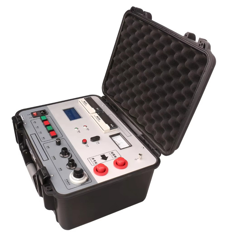
HV Bridge Method 7500V Power Cable Outer Sheath Fault Tester — XHHG521A
Product Overview
The XHHG521A cable outer sheath fault tester is engineered based on the MURRAY bridge principle, delivering precise location of breakdown points across various wire and cable types, including defect points that have not yet fully broken down but exhibit low insulation resistance values.
The equipment utilizes an electric voltage regulator and an R-type transformer to form a high-voltage constant current source, with push-button control for voltage increase or decrease. The no-load voltage reaches 7500V with a short-circuit current of 100mA. A high-sensitivity amplifier and galvanometer indicate bridge balance, working in conjunction with a proportional potentiometer placed at high potential. The measurement cable is a specially designed two-core high-voltage rubber cable, employing a four-terminal resistance measurement method to eliminate lead resistance errors.
With one-touch operation, simply enter the cable length and the fault distance is calculated automatically. The high-voltage source and bridge are integrated into a portable protective case, offering high voltage output, lightweight design, easy operation, and safe usage.
Key Applications
High-voltage bridge method is particularly suitable for:
- High-resistance breakdown points after cable laying, especially linear high-resistance breakdown points that are difficult to burn into low resistance (e.g., cable intermediate joint failures)
- Flashover-type breakdown points — the constant current source maintains the arc post-breakdown, ensuring stable bridge current and sufficient sensitivity
- Pre-breakdown defects with low insulation resistance — defects detected by megohmmeter that have low cable resistance but do not break down under operating voltage
Target Industries & Applications
This equipment is purpose-built for B2B clients in the power infrastructure sector:
- Power Supply Bureaus & Grid Operators — routine diagnostic testing and fault location for urban and rural HV cable networks
- Cable Installation & Construction Contractors — on-site acceptance testing and post-installation fault detection
- Electrical Engineering & Design Institutes — compliance verification and cable system integrity assessment
- High-Voltage Cable Manufacturers — factory quality assurance and pre-delivery insulation testing
- Industrial Facilities & Substations — periodic maintenance and rapid fault diagnosis for in-service cable systems
- Testing & Certification Bodies — third-party verification of cable insulation and sheath integrity
Key Features
- Adjustable output voltage for versatile testing scenarios
- High accuracy and stability with high-sensitivity amplifier and galvanometer balance indication
- Zero-start protection for enhanced operator safety
- Automatic fault point calculation with manual testing override capability
- Bridge balance method eliminates blind spots — ideal for short cable and near-end breakdown point detection, outperforming wave reflection methods
- Integrated high-voltage source and bridge in a single portable protective case
Technical Specifications
| Parameter |
Value |
| No-load Voltage |
≥7500V |
| Short Circuit Current |
≥100mA (5~40mA recommended for balance adjustment) |
| Positioning Accuracy |
±(0.2%·L±1) m |
| Weight |
25 kg |
| Power Supply |
AC 220V (±10%), 50Hz±1Hz; 8.4V built-in battery |
Frequently Asked Questions
Select the most relevant FAQs for your customers from the list below:
Q1: What is the working principle of the XHHG521A cable sheath fault tester?
The XHHG521A operates on the MURRAY bridge principle, using a high-voltage constant current source with a proportional potentiometer to form a balanced bridge. It precisely locates cable sheath faults by measuring resistance ratios and automatically calculating the fault distance from the cable length input.
Q2: What voltage and current levels does this tester provide?
The unit delivers a no-load voltage of ≥7500V and a short-circuit current of ≥100mA. During balance adjustment, it is recommended to operate at 5~40mA for optimal measurement stability and accuracy.
Q3: What types of cable faults can the HV bridge method detect that other methods cannot?
The HV bridge method excels at detecting linear high-resistance breakdown points (especially in cable joints), flashover-type breakdowns where arc maintenance is required, and pre-breakdown insulation defects with low resistance that do not manifest under operating voltage — scenarios where wave reflection methods often fail.
Q4: How does the bridge balance method eliminate testing blind spots?
Unlike wave reflection methods that have inherent blind zones near the test terminals, the bridge balance method measures the entire cable length proportionally from end to end, providing full-range coverage with no dead zones — particularly valuable for short cable sections and near-end fault location.
Q5: What is the positioning accuracy of this equipment?
The positioning accuracy is ±(0.2%·L±1) meters, where L is the total cable length. For example, on a 1000-meter cable, the accuracy is approximately ±3 meters, making it suitable for precise excavation planning and minimizing repair costs.
Q6: Can the XHHG521A operate in the field without mains power?
The unit primarily operates on AC 220V (±10%), 50Hz±1Hz mains power. It also features an 8.4V built-in battery for basic functions and data retention, though full high-voltage testing requires mains connection for consistent 7500V output.
Q7: How does the four-terminal measurement method improve accuracy?
The four-terminal (Kelvin) resistance measurement method uses separate current-carrying and voltage-sensing leads, effectively eliminating measurement errors caused by lead and contact resistance. This ensures the bridge balance reading reflects only the actual cable fault resistance, not the test lead impedance.
Q8: What is the minimum order quantity and typical delivery schedule?
The minimum order quantity is 1 unit with Shipping Time in 5-8 working days. Each unit is shipped in secure wooden packaging. Volume orders may qualify for discounted pricing and priority production scheduling.
Q9: Is operator training or technical support provided with the equipment?
We provide comprehensive English user manuals with detailed operating procedures. Remote technical support is available for troubleshooting. On-site commissioning and operator training programs can be arranged for bulk orders or long-term service agreements.
Q10: How does the automatic fault calculation feature work alongside manual testing?
The one-touch automatic mode allows operators to input the cable length and receive an instant fault distance calculation. The manual testing function is retained for experienced technicians who need to fine-tune balance adjustments in complex scenarios, offering full operational flexibility.


 Your message must be between 20-3,000 characters!
 english
 français
 Deutsch
 Italiano
 Русский
 Español
 português
 Nederlandse
 ελληνικά
 日本語
日本語
 한국
한국
 العربية
 हिन्दी
 Türkçe
 indonesia
 tiếng Việt
 ไทย
ไทย
 বাংলা
বাংলা
 فارسی
فارسی
 polski