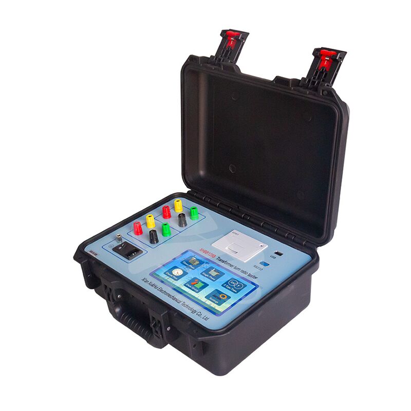
XHBB128B
Power transformer turns ratio/voltage ratio testing is a critical requirement in multiple scenarios: during semi-finished/finished product manufacturing, before new transformer installation and operation, and in line with the Ministry of Electric Power’s preventive test procedures. The test’s key objectives include validating turns ratio accuracy, assessing tap changer performance, detecting inter-turn short circuits, and confirming whether transformers can be operated in parallel. Traditional turns ratio bridge testing is inefficient, with non-intuitive readings and phase-by-phase measurement constraints. The Turns Ratio Tester overcomes these challenges through user-friendly operation and a three-phase precision inverter power supply, delivering fast, high-precision testing results for practical on-site and laboratory applications.
Technical parameters
(1). Test range: 0.9 ~ 10000
(2). Measurement accuracy: ± 0.1% + 2 words (0.9-500)
± 0.2% + 2 words (501-2000)
± 0.5% + 2 words (2001-10000)
(3). Resolution: 0.0001 min
(4). Output voltage: automatically adjust according to the load
(5). Working power supply: AC220V ± 10% 50 ± 1Hz
(6). Ambient temperature: - 10 ℃ ~ 40 ℃
(7). Relative humidity: ≤ 85%, no condensation
Common problems and inspection methods of instrument
When the test is abnormal, the following methods can be used for self inspection, and
the wiring is shown in the figure below:

After connecting the wire, select y-y-0 or d-d-0 as the connection mode, and then press the OK key to start the measurement. The measured value is 1.0000. The above display shows that the instrument is normal, otherwise it is a problem with the instrument.
If there is no short circuit, the yellow, green, red and black wiring pliers on the high-voltage side of the test line can also be short circuited together with the yellow, green, red and black wiring pliers on the low-voltage side (pay attention to the position of the pliers lead during short circuit, and the wired end should be reliably connected together).

 Your message must be between 20-3,000 characters!