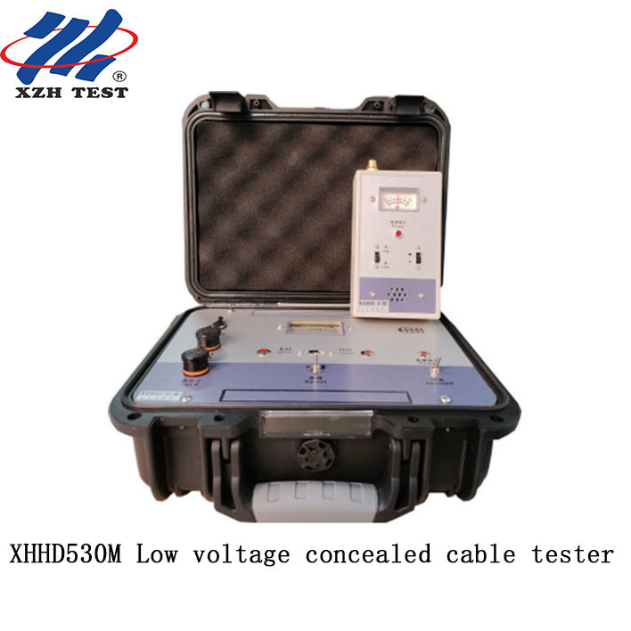
XHHD530M Low voltage concealed cable tester
Description
The hidden line buried line fault detector is a special instrument for power, broadcasting, post and telecommunications departments, as well as industrial and mining, rural areas to find underground cables, including direct buried armored cable lines and buried line faults. It can detect the direction of the buried line, the more accurate underground position, the basic buried depth, and various ground leakage faults, broken core faults, including lines under paddy fields, cement roads, bricks and stones, asphalt roads, and lines in the walls of buildings. Waterproof wires and cables used on the ground can be detected by using this instrument through appropriate methods.
Transmitter
|
The transmitter panel is equipped with "power switch", "power indication"; "output selection", "high, medium, low"; "output indication" and "K measurement" switching switches, and the indicator light indicates the switching position; "output·KΩ measurement" shares an output terminal, which is switched by the "output·indication" and "KΩ measurement" switches; set "output 2" output terminal; square meter head indicates output and KΩ resistance. It can check the line on, off, mixed, and measure the size of the ground leakage resistance.
|
|
Output signal form
|
pulse period 1.34±0.15mS. Width 0.2 ±0.1mS intermittent period 1.8±1S.
|
|
Output voltage
|
pulse period Upp high range greater than 1000V, medium range greater than 60V, low range greater than 30V.
|
|
KΩ measurement
|
It can check the side line on, off, mixed and leakage group size, and determine the nature of the fault.
|
|
The "output 2" output terminal
|
It can output peak pulse short-circuit current 1-5A.
|
|
Output power
|
Pulse power greater than 2.5W (when high-end load resistance is 80KΩ).
|
|
Power supply
|
8.4V.
|
Instrument principle and structure
This instrument consists of a transmitter, a receiver, a probe and a head, a pair of plugs and plugs, connecting wires, etc.
Transmitter (1) Mainly outputs continuous pulse signals, which is the signal source for finding faults. (2) kΩ function, can detect the continuity, disconnection, mixing and leakage resistance of the line, and determine the nature and type of fault. (3) "Output 2" output terminal outputs large current
Packing list
|
Item
|
Name
|
Qty.
|
|
1
|
Transmitter
|
1
|
|
2
|
Receiver
|
1
|
|
3
|
Probe
|
1
|
|
4
|
Probe head
|
1
|
|
5
|
Insert rod(red black)
|
2
|
|
6
|
Connection lines
|
2
|
|
7
|
Charger
|
1
|


 Your message must be between 20-3,000 characters!