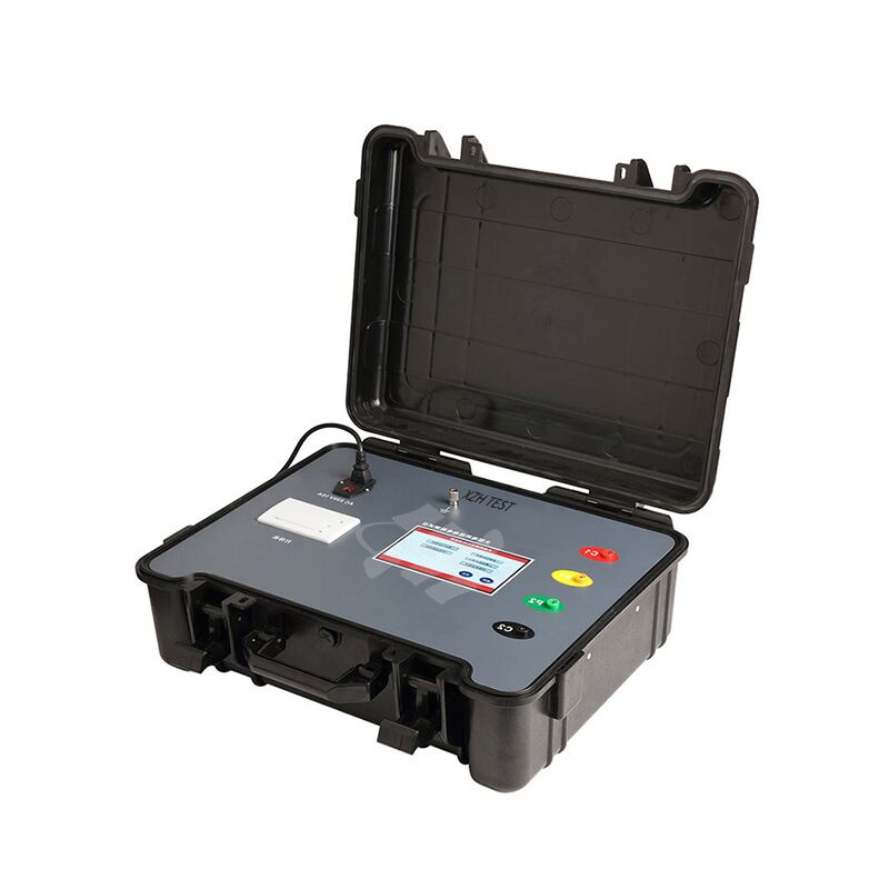
The XHEP701A digital large ground grid grounding resistance tester is used for grounding impedance, soil resistivity, step voltage, distribution potential and contact voltage measurement. It uses a variable-frequency AC source, dual-frequency measurement, a 7-inch touch colour screen and microprocessor control.
The instrument covers 0.030 Ω – 2000 Ω grounding impedance, stores 100 groups and includes a built-in thermal printer. Its output is adjustable from 1 A to 5 A, with maximum open-circuit voltage 400 V and maximum short-circuit current 5 A.
For lightning protection, telecom and computer-room teams that verify grounding and step/contact voltage at sensitive or exposed sites.
| Function | Range | Accuracy / Formula | Resolution |
|---|---|---|---|
| Grounding impedance | 0.030 Ω – 1.999 Ω | ±0.5 % FS ±5 dgt | 0.001 Ω |
| Grounding impedance | 2.00 Ω – 19.99 Ω | ±0.5 % FS ±5 dgt | 0.01 Ω |
| Grounding impedance | 20.0 Ω – 199.9 Ω | ±0.5 % FS ±5 dgt | 0.1 Ω |
| Grounding impedance | 200 Ω – 2000 Ω | ±0.5 % FS ±5 dgt | 1 Ω |
| Soil resistivity | 0.000 Ωm – 9.999 Ωm | ρ = 2πaRX | 0.001 Ωm |
| Soil resistivity | 10.00 Ωm – 99.99 Ωm | ρ = 2πaRX | 0.01 Ωm |
| Soil resistivity | 100.0 Ωm – 999.9 Ωm | ρ = 2πaRX | 0.1 Ωm |
| Soil resistivity | 1000 Ωm – 9999 Ωm | ρ = 2πaRX | 1 Ωm |
| Soil resistivity | 10.0 kΩm – 99.9 kΩm | ρ = 2πaRX | 0.1 kΩm |
| Soil resistivity | 100 kΩm – 999 kΩm | ρ = 2πaRX | 1 kΩm |
| Step voltage / distribution potential / contact voltage | 0.000 kV – 1.999 kV | U = Z × Is | 0.001 kV |
| Step voltage / distribution potential / contact voltage | 2.00 kV – 19.99 kV | U = Z × Is | 0.01 kV |
| Step voltage / distribution potential / contact voltage | 20.0 kV – 199.9 kV | U = Z × Is | 0.1 kV |
| Impedance angle | 0 – 359.9° | — | 0.1° |
| Radian | 0 – 6.283 | — | 0.001 |
| Parameter | Specification |
|---|---|
| Function | Grounding impedance, soil resistivity, step voltage, distribution potential, contact voltage |
| Rated measurement power | 2000 W |
| Anti-interference | 50 Hz voltage 50 V |
| Reference conditions | 23 °C ±5 °C, below 70 % RH; auxiliary ground resistance 20 Ω ±10 %; voltage to ground < 10 V |
| Power supply | AC 220 V 10 A, 50 Hz |
| Backlight | Adjustable brightness |
| Measurement mode | Four-wire, three-wire and two-wire test |
| Measurement method | Grounding impedance: rated current method |
| Short-circuit current output | 1 A, 2 A, 3 A, 4 A, 5 A (5 settings) |
| Soil resistivity electrode spacing | Settable 1 m – 100 m |
| Test frequency | 45 Hz, 55 Hz or automatic dual-frequency |
| Maximum short-circuit current | AC 5 A ±10 %, sine wave |
| Maximum open-circuit voltage | AC 400 V ±10 %, sine wave |
| Display | 7-inch touch colour screen |
| Touch screen | Yes |
| Measurement indication | Measurement progress display and measurement prompt animation |
| Dimensions | 540 mm × 440 mm × 210 mm |
| Standard test line | Red 15 m, black 15 m, yellow 10 m, green 10 m, yellow 1.5 m, green 1.5 m; one each |
| Auxiliary ground rods | 800 mm × 2; 200 mm × 2 |
| Measurement time | Grounding impedance: about 1 minute per test |
| Printer | Built-in thermal printer |
| Print paper | 57 mm × 40 mm |
| Data storage | 100 groups; "Saved" indication; "Save failed, memory full" when full |
| Data review | Yes |
| Overflow display | OL symbol |
| Automatic shut-down | None |
| Power consumption | Standby: < 110 W; measurement: 2000 W |
| Weight | Instrument: 27 kg; test line, auxiliary ground rods and bag: 5.5 kg |
| Working temperature and humidity | -10 °C – 40 °C; below 80 % RH |
| Storage temperature and humidity | -20 °C – 60 °C; below 70 % RH |
| Insulation resistance | ≥ 10 MΩ at 500 V between circuit and case |
| Withstand voltage | AC 3700 V/rms between circuit and case |
| Electromagnetic characteristics | IEC61010-4-3; radio-frequency electromagnetic field ≤ 1 V/m |
| Safety | IEC61010-1; IEC1010-2-31; IEC61557-1, 5; IEC60529 (IP54); pollution degree 2; CAT III 300 V |