XHGG501X
This cable fault locator XHGG501X realizes ABC three-phase cable sampling separately, and the sampling waveform is displayed on the screen at the same time, so that the waveform of the three-phase cable can be compared. The instrument has the functions of adaptive output pulse sampling speed and automatic waveform analysis, and the application is simple.
The cable fault tester is a special instrument for measuring and analyzing the state of power cable and fault distance. The cable fault tester uses modern electronic technology and computer technology to combine high-speed sampling, narrow output pulse, and small blind area to realize signal filtering, acquisition, data processing, waveform display, waveform analysis to complete the cable length test and cable fault distance test.
The cable fault tester is suitable for low resistance, short circuit, open circuit failure of power cable, coaxial cable, street lamp cable, buried wire and other materials of different sections and different media. The technical parameters meet the standard requirements of "DL/T 849.1 General Technical Conditions for special tester for power equipment Part 1: Cable Fault flash Tester" and "JJF1042 Calibration Specification for Cable Fault Tester".
Product characteristics
1. Industrial 6.6 "LCD display, computer control, touch operation mode;
2. With the function of measuring length and fault distance;
3. Automatic continuous sampling, waveform capture timely and accurate;
4. With low voltage pulse method;
5. Built-in large capacity battery pack, easy to use;
6. Use a protective chassis, not lower than PI54.
Working principle
Cable fault tester adopts traveling wave method test principle:
1. Traveling wave method: When the radio wave is transmitted in the transmission line, if the transmission line is not uniform, that is, the characteristic impedance of a point in the transmission line changes, when the radio wave is transmitted to the point, in addition to continuing to transmit to the load, it will also produce reverse transmission and return to the test end, we call the reverse transmission of the wave reflected wave, the phenomenon of the wave producing reverse transmission is called the reflection phenomenon of the wave. The so-called traveling wave refers to the general name of incident wave and reflected wave.
2, when the radio wave is transmitted in the transmission line, the polarity of the echo at the short circuit point is opposite to the polarity of the emitted pulse, and the polarity of the echo at the break point (including the cable terminal) is the same as the polarity of the emitted pulse. Using the pulse method, the instrument can easily determine the distance between the fault point and the test end according to the polarity of the echo.
3. The cable fault tester applies a low-voltage pulse signal to the cable under test, and the pulse signal generates a reflected signal through the fault point of the cable. The cable fault tester processes the reflected signal and presents a waveform diagram. The coarse fault distance of the cable under test is determined by analyzing the reflected waveform.
Panel introduction

1 LCD: interface display;
2 Signal: Connect the signal output line to the cable;
3 Charging: Connect the charger to charge the instrument;
4 Amplitude: amplitude potentiometer, adjust the sampling amplitude;
5 Switch: Power switch.
Instrument display screen
1 Waveform display area: The sampling waveform of ABC three-phase cable can be displayed at the same time;
2 Current moving cursor: The cursor that can currently be moved is displayed in black;
3 Fixed position cursor: After the cursor moves to determine the position, the fixed position cannot be moved. The two cursors are switched by the "Confirm" button;
4 Test results: This data is calculated and set based on the cursor distance. After sampling, it is automatically analyzed and when the cursor is moved, the data changes accordingly;
5 Media speed selection or setting: Select the media speed corresponding to the cable type;
6 Cable length setting: Once the cable length is set, the output pulse width and sampling speed will be automatically set;
7 Current sampling phase settings, ABC three-phase cycle;
8 File processing: reserved;
9 Waveform expansion/waveform movement: the two functions switch to each other;
10 Waveform upward movement: Move the waveform upward in the hold state;
11 Waveform compression/waveform left shift: perform waveform processing in the hold state;
12 Waveform expansion/waveform right shift: perform waveform processing in the hold state;
13 Waveform recovery: displays the phase of the current waveform;
14 Waveform downward movement: Waveform downward movement in the hold state;
15 Step size selection: Select the distance of one movement when the cursor moves;
16 Cursor left: Control the cursor to move left in the hold state;
17 Move the cursor to the right: Control the cursor to move to the left in the hold state;
18 Confirm: After the cursor movement is confirmed, switch the cursor to another one;
19 Automatic analysis: After analyzing the current waveform, determine the positions of the two cursors;
20 Sampling/holding: status prompt;
21 Sample/hold: status switching;
22 Baseline upward shift: The overall sampling waveform moves upward, and the sampling status is valid;
23 Baseline downward shift: the overall sampling waveform moves downward, and the sampling status is valid;
24 Amplitude reduction: The sampling amplitude is reduced, and the sampling status is valid;
25 Amplitude increase: The sampling amplitude increases, and the sampling status is valid;
26 Battery level: Displays the current battery level.
Operation steps and instructions
After connecting the wires, press the power switch, and the system startup interface will appear as shown below:
1 [Velodity] Click velodity settings, and the secondary menu will pop up as follows:
Click to select Set Cable Media Speed. If you need to customize the media speed, click "Customize" and the input speed keyboard will pop up as shown below:
Make settings. The maximum value set is 999.9.
2 [Cable length]
Click the cable length setting to pop up the input cable length keyboard as shown below:
The maximum cable length is 9999.9 meters.
After the cable length is set, the pulse width and sampling speed are automatically set accordingly.
| Cable length |
Sampling frequency |
Pulse Width |
| A less than 100 meters |
200MHz |
0.1us |
| B 100 meters to 500 meters |
100MHz |
0.2us |
| C 500 meters to 1000 meters |
50MHz |
0.5us
|
| D 1000 meters to 2000 meters |
20MHz |
0.75us |
| E greater than 2000 meters |
10MHz |
1us |
3 [Test Phase] Select the test phase, click the test phase, and the ABC three-phase cycle is displayed here. The sampling waveform corresponds to the current one, and the test phase prompt in the middle of the four direction keys changes synchronously with the settings here.
4. After selecting the signal parameters, press [Sampling] to start sampling the feedback signal, and connect the sampling port to the core wire of the cable under test and ground through a dedicated single Q line. (It is strictly prohibited to measure when the cable is live or stored).
The window displays the waveform and is constantly refreshed. During the waveform sampling process, the pulse amplitude may be distorted up and down, and the pulse waveform amplitude is incompletely displayed. You need to click [Shift up] [Shift down] to display the complete pulse amplitude of the waveform. When a frame of suitable waveform is collected, you can press [Keep] to stop sampling and the waveform stops refreshing, as shown in the following figure:
5.Waveform analysis
Click on the upper right corner, and [Waveform Expansion] will be displayed in a loop. This button determines the current function of the four direction keys.
①Waveform expansion function. The button to the left is the compression function, which can be compressed three times to fully display all waveform data. The button to the right is the extended function. Expand the compressed waveform.
②Waveform movement function. The four direction keys, up, down, left and right, correspond to the movement direction of the waveform.
The middle of the four direction keys displays the phase corresponding to the current operation, and the waveform of the current phase returns to the initial state after clicking.
6. Step size selection: Move the cursor left and right and click once to select the distance the cursor can move in one move. After clicking, a secondary menu will pop up as shown in the figure below. Four levels are available. The larger the value, the greater the distance the cursor moves at one time.
Click to select the corresponding moving step size.
7 [Move cursor left] [Move cursor right] After clicking the cursor left and right movement key, you can currently move the cursor by the number of points corresponding to the selected step. When the cursor moves to the appropriate position, click the [Confirm] button to fix the moved points. cursor, the cursor turns white, the other cursor becomes movable, and the cursor is set to black. Click the left and right move buttons to move the cursor.
8 [Automatic analysis] The waveform has been automatically analyzed during sampling, and the corresponding cursor position is set according to the analysis results. After moving the cursor, if you need to automatically analyze the current waveform again, you can click this button to automatically analyze the currently selected waveform again and set the position corresponding to the cursor. Then the calculation of the end point distance is completed and the data is displayed. S=xxxx.xxm in the lower right corner of the screen.
9 When you need A.B.C three-phase waveforms to be displayed at the same time, just click [Phase] to switch the wiring position and follow the steps below:
- Select [Phase] as phase A, click Sampling, and when a suitable waveform is collected, press [Keep], as shown in the figure below:
- Select [Phase] as phase B, switch the wiring position, and click Sample. When a suitable waveform is collected, press [Keep], as shown in the figure below:
- Select [Phase] as phase C, switch the wiring position, and click Sample. When a suitable waveform is collected, press [Keep], as shown in the figure below:
The A-phase waveform is yellow, the B-phase waveform is green, and the C-phase waveform is red. The A.B.C three-phase waveforms are displayed at the same time. If you need to analyze the waveforms separately, click [Phase] to select the corresponding phase for analysis.
10 [Sampling Status]/[Keep Status] is a reminder of the sampling and hold button function. Here, the switching of the sample and hold function is coordinated with the operation of the signal clip. In the hold state, the device enters the waiting state. In this state, the signal line is connected to the cable to be tested, the media speed is set, the cable length is set, and the waveform can be operated. When the signal line is connected and the test parameter setting is completed, it enters the sampling state. At this time, the potentiometer on the panel can be adjusted. The amplitude on the interface increases and decreases, and the baseline moves up and down.
11 [Shift up] [Shift down] The baseline moves up and down. During the waveform sampling process, the pulse amplitude may be distorted up and down, and the pulse waveform amplitude is incompletely displayed. It is even more necessary to move the baseline up and down to display the complete pulse amplitude of the waveform.
12 [Amplitude increase] [Amplitude decrease] Amplitude increase or decrease. When the amplitude potentiometer on the panel adjusts the amplitude of the pulse or the baseline fluctuation is relatively large, the signal amplitude can be amplified or compressed again here.
13 Battery level reminder. This graph represents the percentage of charge. When the icon appears, it means the battery is almost exhausted. Please charge as soon as possible.
Introduction to wiring and testing procedures (on-site operation instructions)
The wiring method is as follows: Use a single Q line to connect the "sampling interface" of the cable fault tester to the faulty phase line and cable shielding layer. The low voltage pulse wiring is shown in the figure below.
Note: During the test, it must be confirmed that there is no electricity stored in the cable body.
Step 1: Clamp the signal line to test phase A. The test phase selection of the corresponding interface is also set to phase A. Then click the sample/keep button on the interface to enter the sampling state. Observe the sampling waveform. If you think the sampling waveform is good, click the sample/keep button to enter the hold state for waveform analysis. Refer to "Waveform" Example -Analyze waveforms.
Step 2: Clamp the signal line to test phase B. Repeat the first step of the testing process.
Step 3: Clamp the signal line to test phase C. Repeat the first step of the testing process.
After the above three-step test is completed, the interface displays the pulse test waveforms of the three-phase cable at the same time.
Packing list: 1. the main tester -1 unit 2.Test cable(single Q line)-1pcs 3. Charger -1pcs
This instrument is especially suitable for measuring open circuit, short circuit, broken circuit and low resistance fault length.
English system can be customized.

 Your message must be between 20-3,000 characters!
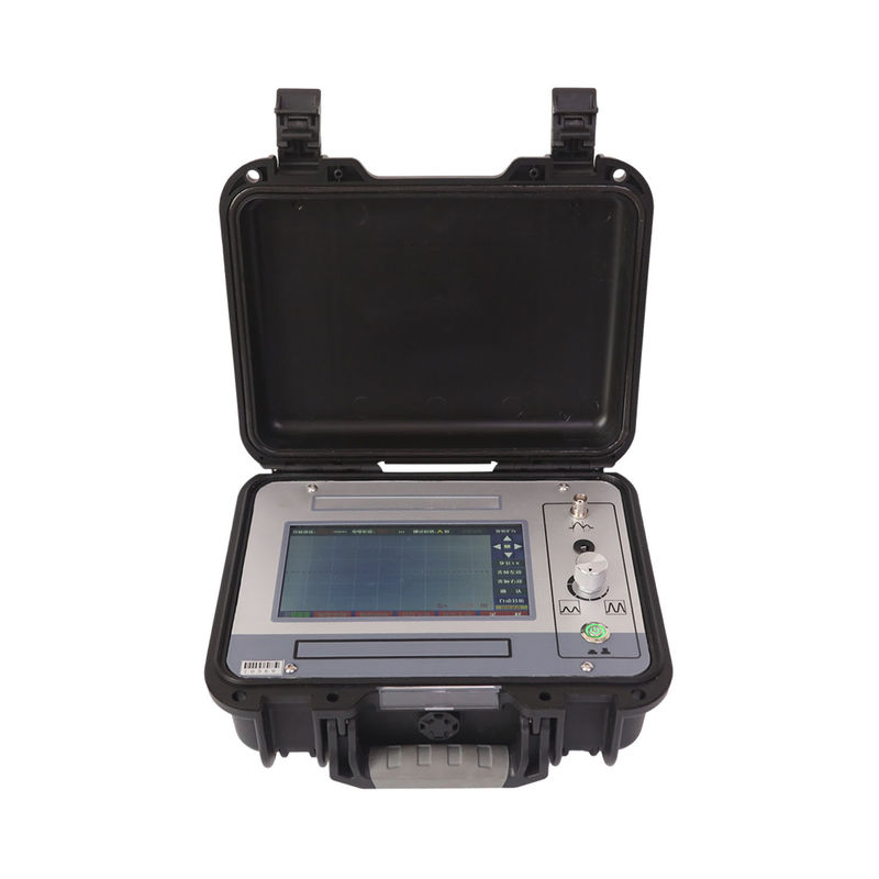
Overall Rating
Rating Snapshot
The following is the distribution of all ratingsAll Reviews